Lighting device and lighting system
A lighting device and light source technology, which is applied in the field of lighting systems, can solve problems such as luminous color switching malfunctions, and achieve the effect of suppressing malfunctions
- Summary
- Abstract
- Description
- Claims
- Application Information
AI Technical Summary
Problems solved by technology
Method used
Image
Examples
Embodiment approach 1
[0020] The lighting device and lighting system according to Embodiment 1 will be described.
[0021] [1-1. Configuration of lighting device and lighting system]
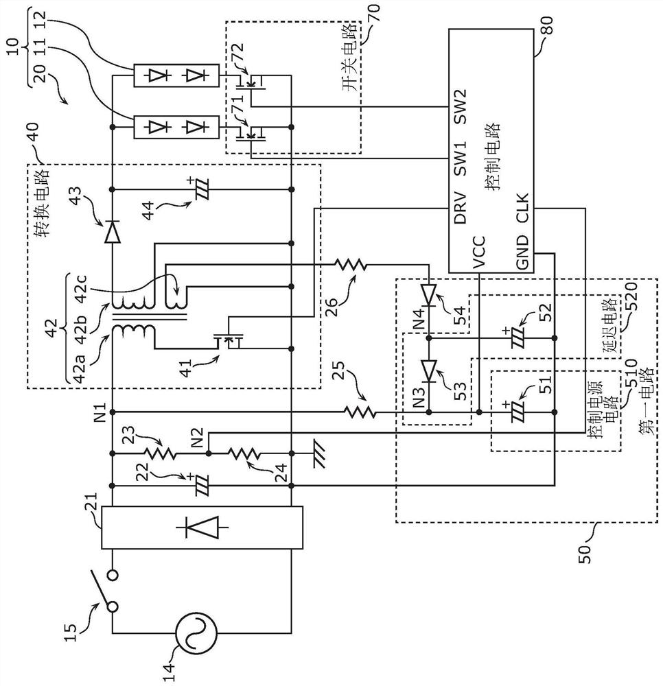
[0022] The configuration of the lighting device and the lighting system according to the present embodiment will be described with reference to the drawings.
[0023] figure 1 It is a circuit diagram showing an example of the circuit configuration of the lighting device 20 and the lighting system 10 according to this embodiment. and, in figure 1 A power supply 14 for supplying electric power to the lighting system 10 and a power switch 15 for turning on or off the lighting system 10 are also shown in the figure. The power supply 14 is, for example, a system power supply such as a commercial power supply whose output voltage is an alternating current of 100V.
[0024] The power switch 15 is a switch provided on a wire that supplies power from the power source 14 to the lighting system 10 . When the power switch 1...
Embodiment approach 2
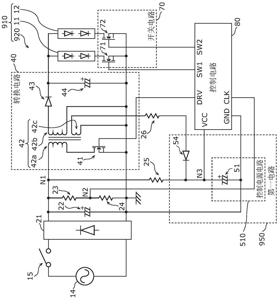
[0075] A lighting device and lighting system according to Embodiment 2 will be described. The lighting device and the lighting system according to this embodiment have a configuration that suppresses uneven operation. Hereinafter, this embodiment will be described focusing on differences from Embodiment 1. FIG. First, the configuration of the lighting device and the lighting system according to the present embodiment will be described with reference to the drawings. Figure 4 It is a circuit diagram showing an example of the circuit configuration of the lighting device 120 and the lighting system 110 according to this embodiment.
[0076] Such as Figure 4 As shown, the lighting device 120 and the lighting system 110 according to the present embodiment are different from the lighting device 20 and the lighting system 10 according to the first embodiment in the configuration of the first circuit 150 . Hereinafter, the configuration of the first circuit 150 according to the p...
Embodiment approach 3
[0085] A lighting device and lighting system according to Embodiment 3 will be described. The lighting device and the lighting system according to the present embodiment have a structure capable of reliably performing a reset operation of the control circuit, that is, a structure capable of reliably reducing the control voltage. Hereinafter, the present embodiment will be described focusing on differences from the second embodiment. First, the configuration of the lighting device and the lighting system according to the present embodiment will be described with reference to the drawings. Figure 6 It is a circuit diagram showing an example of the circuit configuration of the lighting device 220 and the lighting system 210 according to this embodiment.
[0086] Such as Figure 6 As shown, the lighting device 220 and the lighting system 210 according to the present embodiment are different from the lighting device 120 and the lighting system 110 according to the second embodim...
PUM
 Abstract
Description
Claims
Application Information
 - R&D
- Intellectual Property
- Life Sciences
- Materials
- Tech Scout
- Unparalleled Data Quality
- Higher Quality Content
- 60% Fewer Hallucinations
Browse by: Latest US Patents, China's latest patents, Technical Efficacy Thesaurus, Application Domain, Technology Topic, Popular Technical Reports.
© 2025 PatSnap. All rights reserved.Legal|Privacy policy|Modern Slavery Act Transparency Statement|Sitemap|About US| Contact US: help@patsnap.com


