Petroleum pipeline cleaning device

A technology for cleaning equipment and oil pipelines, which is applied in the directions of cleaning hollow objects, cleaning methods and utensils, and cleaning methods using tools, etc., and can solve the problems of large oil pipelines, inconvenient cleaning, time-consuming and labor-intensive, etc.

Inactive Publication Date: 2018-02-23
赵卫祥
View PDF6 Cites 3 Cited by
  • Summary
  • Abstract
  • Description
  • Claims
  • Application Information

AI Technical Summary

Problems solved by technology

[0005] In order to overcome the shortcomings of time-consuming and labor-intensive labor-intensive cleaning of petroleum pipelines manually, and the large petroleum pipelines make it inconvenient for people to clean them, the technical problem to be solved by the present invention is to provide a time-saving, labor-saving and labor-intensive , the oil pipeline cleaning equipment that can fully clean the oil pipeline

Method used


Image

  • Petroleum pipeline cleaning device
  • Petroleum pipeline cleaning device
  • Petroleum pipeline cleaning device

Examples


Embodiment 1

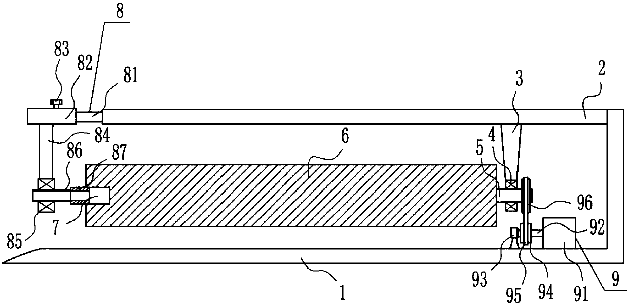
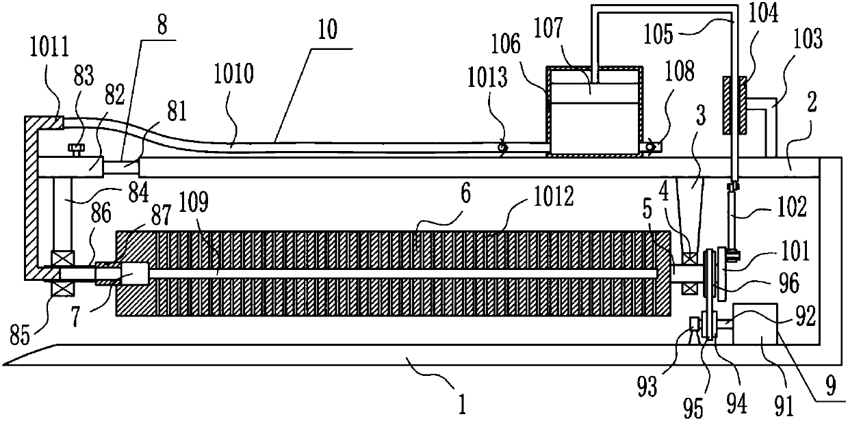
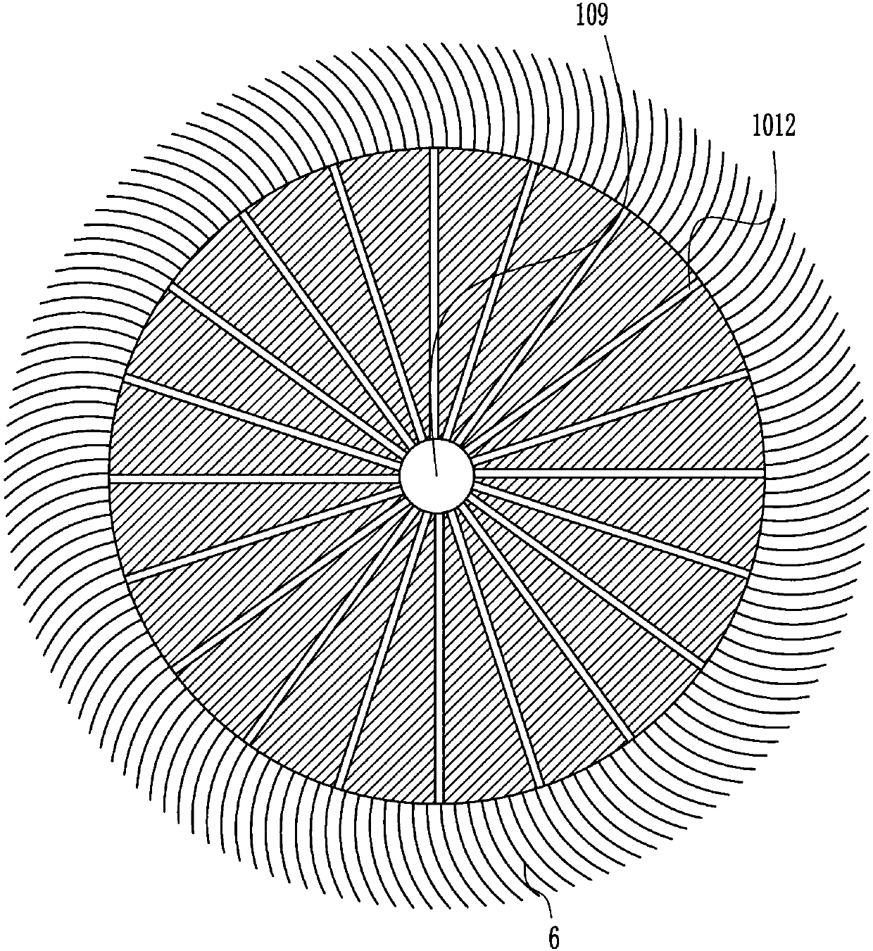
[0030] A kind of oil pipeline cleaning equipment, such as Figure 1-6 As shown, it includes an L-shaped plate 1, a top plate 2, a support seat 3, a first bearing seat 4, a rotating shaft 5, a rolling brush 6, a support device 8 and a driving device 9, and a top plate is installed on the upper right side of the L-shaped plate 1. 2. A support seat 3 is installed on the right side of the bottom of the top plate 2, a first bearing seat 4 is installed on the bottom of the support seat 3, and a rotating shaft 5 is installed in the first bearing seat 4, between the right end of the rotating shaft 5 and the right side of the inner bottom of the L-shaped plate 1 A driving device 9 is provided, a rolling brush 6 is installed at the left end of the rotating shaft 5, a rectangular groove 7 is provided at the center of the circle on the left side of the rolling brush 6, and a supporting device 8 is provided on the left side of the top plate 2, and the supporting device 8 cooperates with the...

Embodiment 2

[0032] A kind of oil pipeline cleaning equipment, such as Figure 1-6 As shown, it includes an L-shaped plate 1, a top plate 2, a support seat 3, a first bearing seat 4, a rotating shaft 5, a rolling brush 6, a support device 8 and a driving device 9, and a top plate is installed on the upper right side of the L-shaped plate 1. 2. A support seat 3 is installed on the right side of the bottom of the top plate 2, a first bearing seat 4 is installed on the bottom of the support seat 3, and a rotating shaft 5 is installed in the first bearing seat 4, between the right end of the rotating shaft 5 and the right side of the inner bottom of the L-shaped plate 1 A driving device 9 is provided, a rolling brush 6 is installed at the left end of the rotating shaft 5, a rectangular groove 7 is provided at the center of the circle on the left side of the rolling brush 6, and a supporting device 8 is provided on the left side of the top plate 2, and the supporting device 8 cooperates with the...

Embodiment 3

[0035] A kind of oil pipeline cleaning equipment, such as Figure 1-6 As shown, it includes an L-shaped plate 1, a top plate 2, a support seat 3, a first bearing seat 4, a rotating shaft 5, a rolling brush 6, a support device 8 and a driving device 9, and a top plate is installed on the upper right side of the L-shaped plate 1. 2. A support seat 3 is installed on the right side of the bottom of the top plate 2, a first bearing seat 4 is installed on the bottom of the support seat 3, and a rotating shaft 5 is installed in the first bearing seat 4, between the right end of the rotating shaft 5 and the right side of the inner bottom of the L-shaped plate 1 A driving device 9 is provided, a rolling brush 6 is installed at the left end of the rotating shaft 5, a rectangular groove 7 is provided at the center of the circle on the left side of the rolling brush 6, and a supporting device 8 is provided on the left side of the top plate 2, and the supporting device 8 cooperates with the...


PUM


Abstract

The invention relates to a cleaning device, in particular to a petroleum pipeline cleaning device. Against technical problems to be solved, the invention provides a petroleum pipeline cleaning devicewhich can save time and labor, is small in labor intensity and can comprehensively clean the inside of a petroleum pipeline. In order to solve the technical problems, the invention provides the petroleum pipeline cleaning device which includes an L-shaped plate and a top plate and the like. The top plate is mounted on the upper portion of the inner right side of the L-shaped plate, a supporting seat is mounted on the right side of the bottom of the top plate, a first bearing block is mounted at the bottom of the supporting seat, a rotating shaft is mounted in the first bearing block, a drivingdevice is disposed between the right end of the rotating shaft and the right side of the inner bottom of the L-shaped plate, and a rolling brush is mounted at the left end of the rotating shaft. According to the petroleum pipeline cleaning device, through a water spraying device, water does not need to be poured in the petroleum pipeline manually, so that the petroleum pipeline cleaning device saves time and labor; through a clamping device, the petroleum pipeline can be fixed, to prevent the petroleum pipeline from moving and affecting cleaning effects, and effects of saving time and labor and being small in labor intensity and capable of comprehensively cleaning the inside of the petroleum pipeline are achieved.

Description

technical field [0001] The invention relates to a cleaning device, in particular to an oil pipeline cleaning device. Background technique [0002] Oil pipelines are composed of oil pipes and their accessories, and are equipped with corresponding oil pump units according to the needs of the process, designed and installed as a complete pipeline system to complete the tasks of oil loading, unloading and transportation. [0003] Oil pipelines need to be cleaned before laying to prevent the impurities in the oil pipelines from affecting the quality of the oil. When cleaning the oil pipelines manually, it is time-consuming, labor-intensive, and labor-intensive. The oil pipelines are large and inconvenient for people to clean. Therefore There is an urgent need to develop an oil pipeline cleaning equipment that saves time and labor, has low labor intensity, and can fully clean the inside of the oil pipeline. Contents of the invention [0004] (1) Technical problems to be solved ...

Claims


Application Information

Patent Timeline
Patent Type & Authority Applications(China)
IPC IPC(8): B08B1/04B08B9/045
CPCB08B1/04B08B9/045
Inventor 赵卫祥卢雪萍李晓婷
Owner 赵卫祥
Why Eureka
Try Eureka