Puller

A technology of the main body and the matching part, which is applied to the puller. field, it can solve problems such as poor clamping, inability to effectively disassemble, and changes, and achieve the effects of simple structure, guaranteed reliability, and convenient use

Pending Publication Date: 2018-02-23
SUZHOU TINGYIHUA AUTOMATION EQUIP CO LTD
View PDF0 Cites 1 Cited by
  • Summary
  • Abstract
  • Description
  • Claims
  • Application Information

AI Technical Summary

Problems solved by technology

[0002] The puller is widely used in machinery. It can disassemble round workpieces such as pulleys, gears, bearings, etc. in various mechanical equipment. It has the advantages of convenient use and stable disassembly. Although the size of the horse can be adjusted within a certain range, the angle of the hook part relative to the workpiece will change after the size adjustment, resulting in weak clamping and effective disassembly.

Method used


Image

  • Puller
  • Puller

Examples


Embodiment Construction

[0017] The technical solution of the present invention will be described in further non-limiting detail below in combination with preferred embodiments and accompanying drawings.

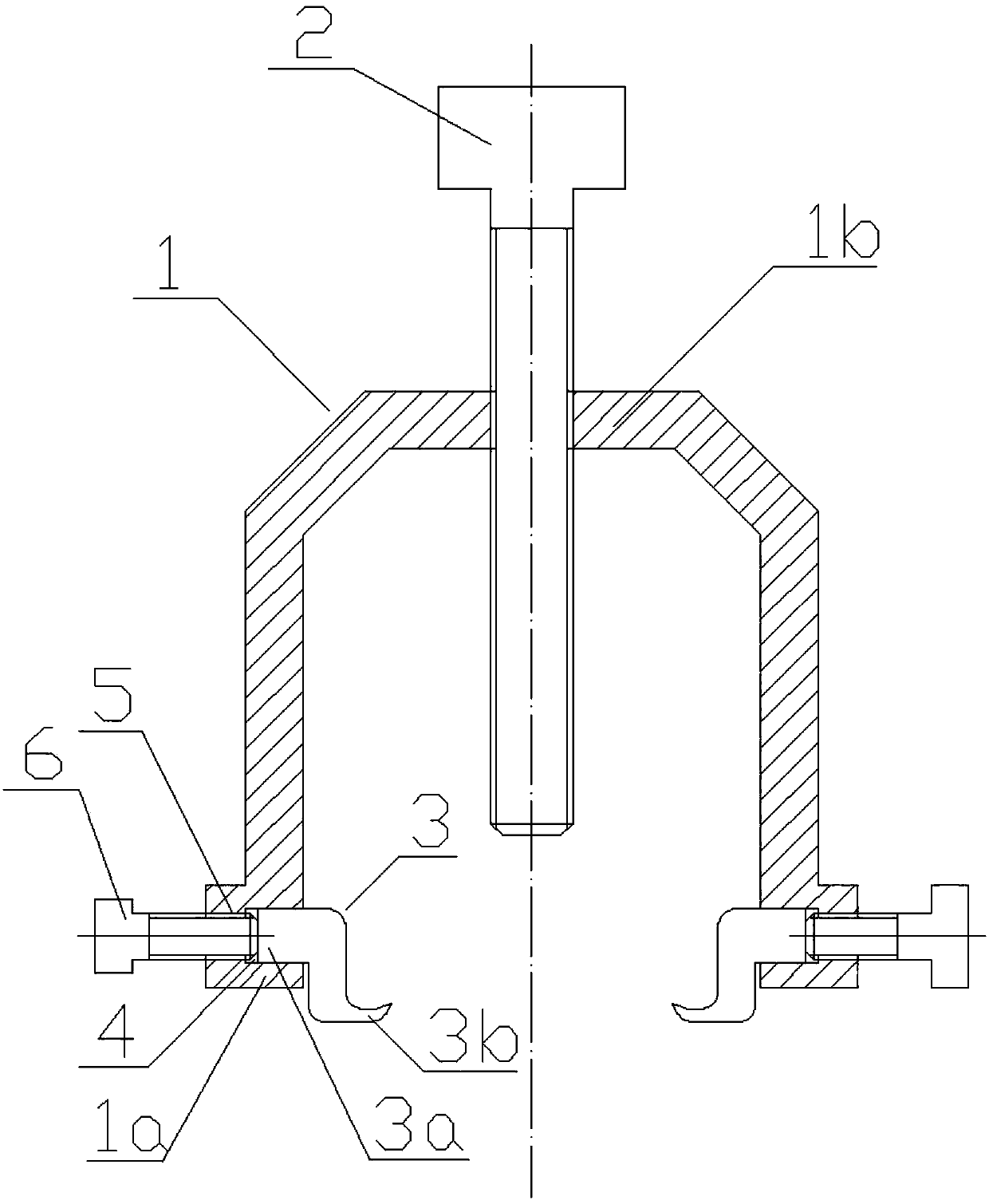
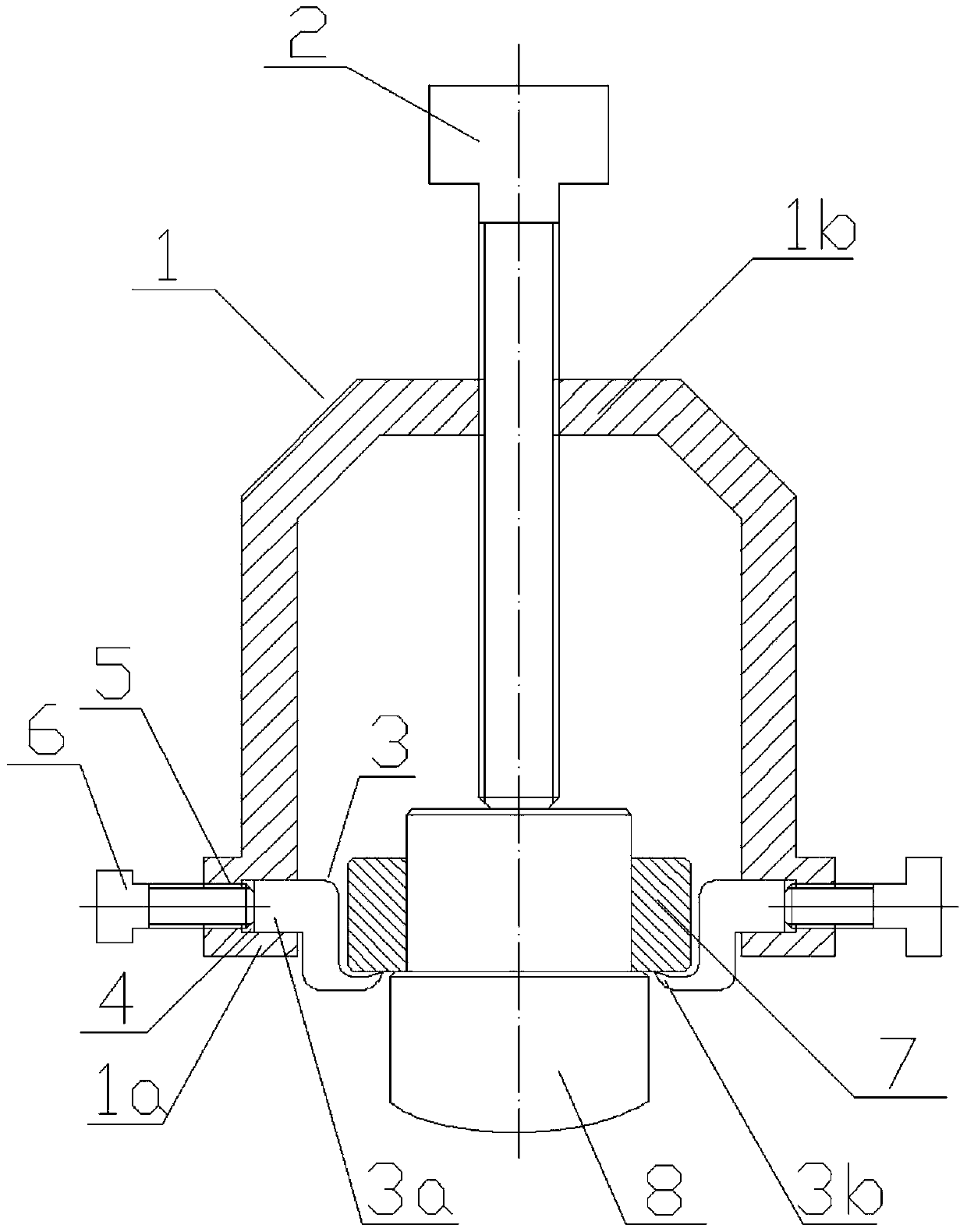
[0018] Such as figure 1 As shown, the puller corresponding to a preferred embodiment of the present invention is used to disassemble the ring-shaped workpiece 7 from the shaft 8, and the workpiece 7 can be workpieces such as bearings, pulleys and gears. The puller includes a body 1 , an extruding screw 2 and a hook 3 .

[0019] The body 1 includes at least two ends 1a that work together to clamp the workpiece 7. The body 1 also includes a connecting portion 1b connecting each end. The extruding screw 2 is arranged at the center of the connecting portion 1b. When the puller clamps the workpiece 7 , the axis of the extruding screw 2 is basically consistent with the axis of the workpiece 7 . In this embodiment, the body 1 is U-shaped, which includes two opposite end portions 1a.

[0020] A hooking m...


PUM


Abstract

The invention discloses a puller, comprising a body (1), an extruding screw (2) threadedly connected with the body (1), the body (1) includes at least two ends (1a), the The end part (1a) is used to hook the ring-shaped workpiece (7), and it is characterized in that: the hooking part (3) is movably connected to the end part (1a), and the hooking part (3) can face the workpiece (7) Move in the direction of the axis. The puller of the present invention can be adjusted in size according to the size of the workpiece, and the angle of the hook portion relative to the workpiece does not change, and the puller is convenient to use and has high reliability.

Description

technical field [0001] The present invention relates to a puller. Background technique [0002] Pullers are widely used in machinery. They can disassemble round workpieces such as pulleys, gears, and bearings in various mechanical equipment. They have the advantages of convenient use and smooth disassembly. Although the size of the horse can be adjusted within a certain range, the angle of its hook portion relative to the workpiece will change after the size is adjusted, resulting in weak clamping and effectively dismounting. Contents of the invention [0003] The purpose of the present invention is to solve the above-mentioned defects in the prior art, and provide a puller, the clamping distance of which can be easily adjusted according to the size of the workpiece, and the angle of the hook will not change. [0004] In order to achieve the purpose of the above invention, the present invention adopts the following technical solution: a puller, including a body, an extrus...

Claims


Application Information

Patent Timeline
Patent Type & Authority Applications(China)
IPC IPC(8): B25B27/02
CPCB25B27/023
Inventor 杨琦
Owner SUZHOU TINGYIHUA AUTOMATION EQUIP CO LTD
Why Eureka
Try Eureka