Quick-dismountable unmanned aerial vehicle propeller fixing mechanism

A technology for fixing a mechanism and a propeller, which is applied to propellers, motor vehicles, aircraft parts, etc., can solve the problems of inconvenient disassembly and assembly of the propeller of drones, and achieve the effects of simple structure, convenient operation and corrosion prevention.

Inactive Publication Date: 2018-02-23
ZHENGZHOU QISHUO ELECTRONICS TECH CO LTD
View PDF0 Cites 2 Cited by
  • Summary
  • Abstract
  • Description
  • Claims
  • Application Information

AI Technical Summary

Problems solved by technology

[0005] The purpose of the present invention is: in order to solve the problem of inconvenient disassembly and assembly of the UAV propeller in the prior art, the present invention provides a fast detachable UAV propeller fixing mechanism

Method used


Image

  • Quick-dismountable unmanned aerial vehicle propeller fixing mechanism
  • Quick-dismountable unmanned aerial vehicle propeller fixing mechanism
  • Quick-dismountable unmanned aerial vehicle propeller fixing mechanism

Examples


Embodiment 1

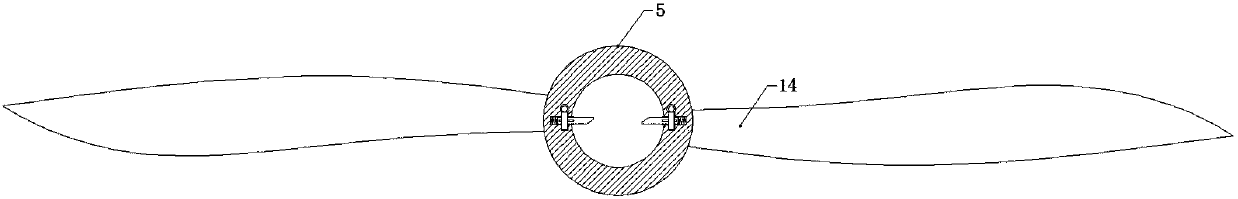
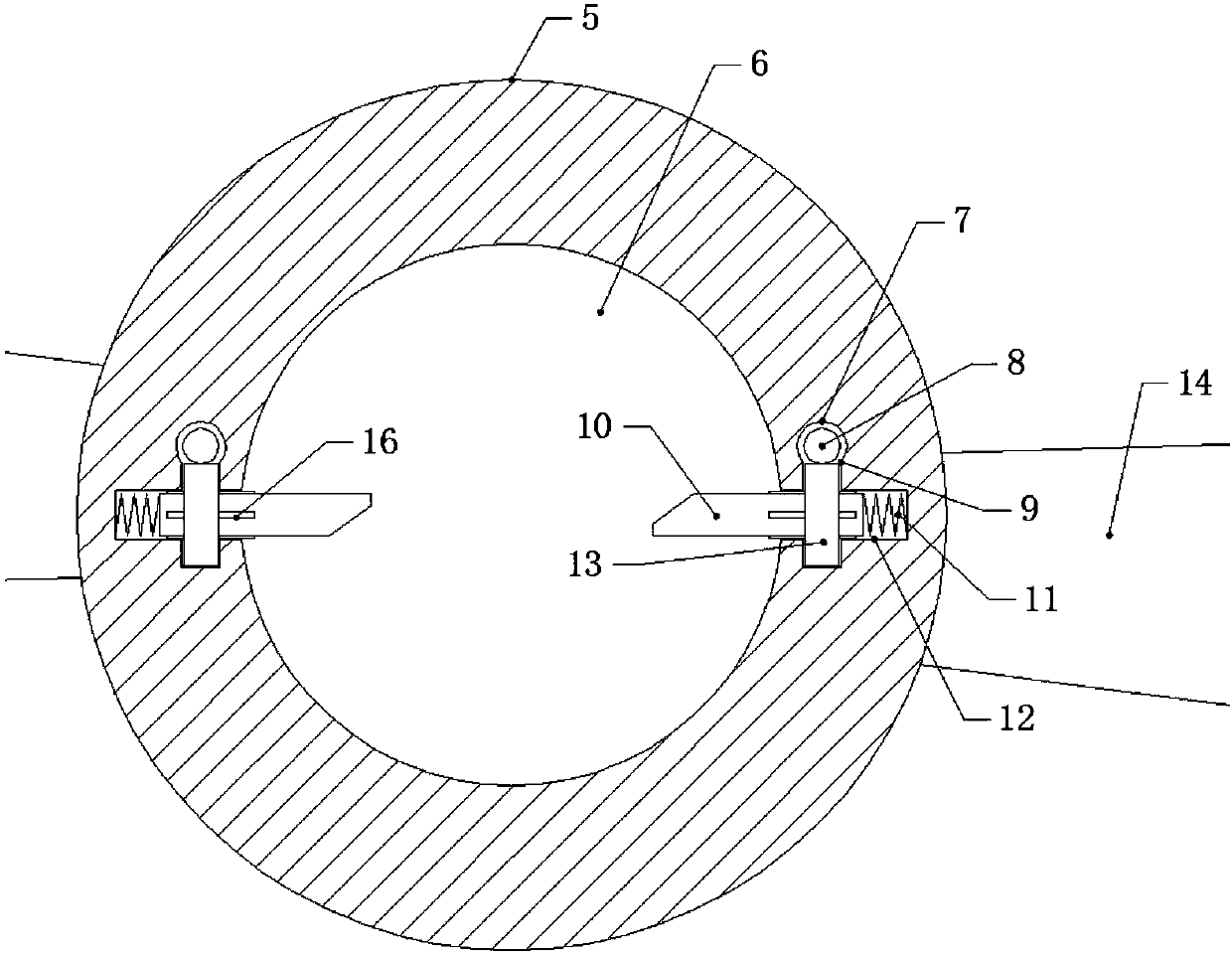
[0027] A quick-detachable UAV propeller fixing mechanism, including the propeller and the rotating shaft 1 arranged on the UAV, is characterized in that: the rotating shaft 1 is symmetrically arranged on the circumference of the rotating shaft. The ends of the chute 2 are respectively connected with a spiral chute 3, and the end of the spiral chute 3 is provided with a limit hole 4, the depth of the limit hole 4 is greater than the depth of the spiral chute 3, and the propeller includes a shaft sleeve 5 and two sides of the shaft sleeve 5. The blades 14 are symmetrically arranged, the center of the shaft sleeve 5 is a shaft hole, and the inner wall of the shaft hole 6 is horizontally and radially provided with two symmetrical fixing holes 12, and the end surface of the shaft sleeve 5 is symmetrically provided with locking holes 7 on both sides of the shaft hole 6, A cylindrical fixed block 10 is arranged in the fixed hole 12, and the end of the fixed block 10 is provided with a...

Embodiment 2

[0032] This embodiment is improved on the basis of Embodiment 1:

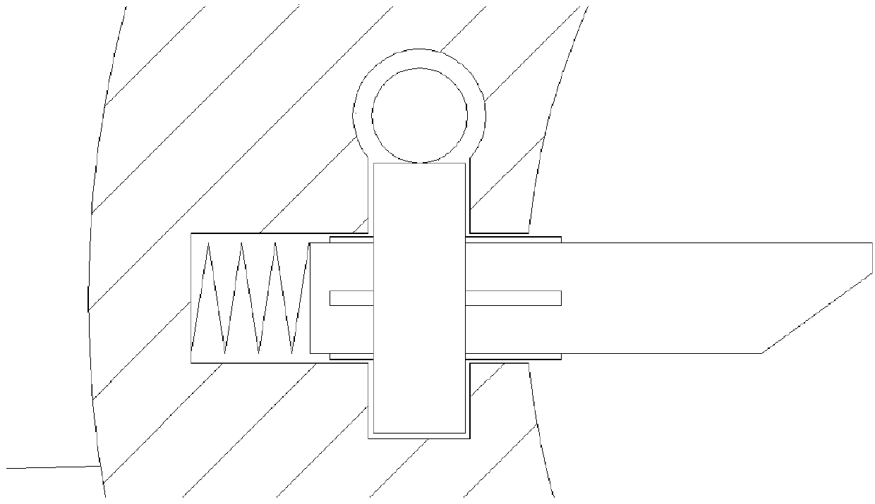
[0033] Splines 16 are arranged on the outer wall of the fixed block 10 , and the worm wheel 13 can slide relatively on the fixed block 10 along the splines 16 .

[0034] The advantage of the above improvements is that the spline can drive the fixed block to rotate through the rotation of the worm wheel, and at the same time can make the worm wheel slide on the surface of the fixed block, so as not to affect the expansion and contraction of the fixed block in the fixed hole.

Embodiment 3

[0036] This embodiment is improved on the basis of the above embodiments:

[0037] The top of the worm 8 is provided with a rotary handle 18, and the shaft sleeve 5 is provided with an openable and closable protective cover 17 on the side end face provided with the locking hole 7.

[0038] The advantages of the above improvements are that the protective cover can protect the fixing device on the shaft sleeve during the flight of the UAV, prevent foreign matter from entering the device and affect the normal function of the device, and also prevent the device from being corroded by water ingress in rainy days.


PUM


Abstract

The invention discloses a quick-detachable UAV propeller fixing mechanism, relates to the technical field of propeller UAVs, and solves the problem of inconvenient disassembly and assembly of UAV propellers in the prior art. The invention includes a propeller and a rotating shaft, and the propeller includes The shaft sleeve is provided with a fixing hole, and a fixed block with a spring at the top is arranged in the fixed hole, and a worm wheel is set on the fixed block, and a locking hole with a worm is also arranged on the shaft sleeve. Cooperate, there is a chute on the rotating shaft, and a limit hole is set at the end of the chute. The fixed block is fixed by sliding into the limit hole in the chute, so as to fix the propeller. When disassembling, the worm wheel and the fixed block are driven to rotate by rotating the worm , so that the inclined plane of the fixed block is rotated to face the chute, and the fixed block shrinks into the fixed hole during the extrusion of the inclined plane and the limiting hole by rotating the propeller, so that the propeller is separated from the rotating shaft.

Description

technical field [0001] The present invention relates to the technical field of propeller unmanned aerial vehicles, and more specifically relates to a fast detachable unmanned aerial vehicle propeller fixing mechanism. Background technique [0002] Unmanned aircraft, referred to as "unmanned aerial vehicle", or "UAV" in English, is an unmanned aircraft that is controlled by radio remote control equipment and its own program control device, or is completely or intermittently operated autonomously by an on-board computer. [0003] Drones are often better suited for missions that are too "dumb, dirty or dangerous" than manned aircraft. According to the application field, UAV can be divided into military and civilian. In terms of military use, UAVs are divided into reconnaissance aircraft and target aircraft. In terms of civilian use, drones + industry applications are the real rigid needs of drones; currently, they are used in aerial photography, agriculture, plant protection,...

Claims


Application Information

Patent Timeline
Patent Type & Authority Applications(China)
IPC IPC(8): B64C39/02B64C11/00B64D45/00
CPCB64C39/02B64C11/00B64D45/00
Inventor 高翔
Owner ZHENGZHOU QISHUO ELECTRONICS TECH CO LTD
Why Eureka
Try Eureka