Supercharge Your Innovation With Domain-Expert AI Agents!

a mechanical lock

A mechanical lock and disc technology, applied in the field of mechanical locks, can solve the problems of easy cracking of the security of mechanical locks, and achieve the effects of reducing the possibility of loss, improving confidentiality and ingenious structure.

Active Publication Date: 2019-10-29
林立荣
View PDF4 Cites 0 Cited by
  • Summary
  • Abstract
  • Description
  • Claims
  • Application Information

AI Technical Summary

Problems solved by technology

[0005] In view of the above situation, in order to overcome the defects of the prior art, the present invention provides a mechanical lock, which effectively solves the problem that the security of the existing mechanical lock is easily cracked

Method used


Image

  • a mechanical lock
  • a mechanical lock
  • a mechanical lock

Examples


Embodiment Construction

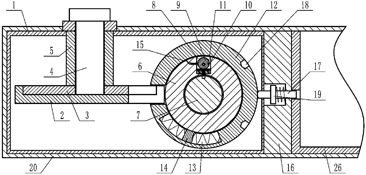
[0025] The specific embodiments of the present invention will be described in further detail below in conjunction with the accompanying drawings.

[0026] by Figure 1 to Figure 15 Given that the present invention includes a control box 1, a horizontal and rotatable first disc 2 inside the control box 1, and a circular recess coaxial with the first disc 2 on the upper end surface of the first disc 2, There is a second disc 3 in the circular pit. The upper end surface of the second disc 3 and the upper end surface of the first disc 2 are on the same plane. The first disc 2 and the second disc 3 constitute a clamping plate, The plate is provided with notches that penetrate radially and vertically; the upper side plate of the control box 1 has a vertical and rotatable first shaft 4, and the upper end of the first shaft 4 penetrates the upper side plate of the control box 1 and is placed in the control box. Above the upper side plate of the box 1, the lower end of the first shaft 4 ...


PUM


Abstract

The invention provides a mechanical lock. The mechanical lock effectively solves the problem that the safety of an existing mechanical lock is prone to being cracked. According to the achieved technical scheme, the mechanical lock comprises a control box; a first disc is arranged in the control box and provided with a second disc, and a clamping plate is formed and provided with a notch; the control box is provided with a first shaft, the first shaft is provided with a sleeve, an annular plate is arranged on the right side of the first disc and provided with a second shaft, the annular plate is provided with a first blind hole, and the first blind hole is provided with a disc-shaped cam; a through hole is formed in the bottom of the first blind hole and internally provided with a pin; thepin is provided with a reset spring, and the second shaft is provided with a clamping hole; the annular plate is provided with an annular ring, the annular ring is provided with a first arc groove, afirst sliding block is arranged in the first arc groove and fixed to the annular plate, and a clamping mechanism is arranged on a right side plate of the control box; and the mechanical lock is ingenious in structure, the defect that the existing mechanical lock is prone to being cracked is effectively overcome, the security of the mechanical lock is greatly improved, and the possibility of important object losing is reduced.

Description

Technical field [0001] The invention relates to the technical field of security machinery, in particular to a mechanical lock. Background technique [0002] At present, the marble and blade lock cylinders on the market usually require a key to be inserted into the lock hole, and the lock can be opened when the key is turned under normal conditions. The lock cylinder of this kind of lock is provided with a rotatable keyhole shaft and a non-rotatable lock cylinder seat. One or more rows of marbles are arranged on one side of the keyhole. There is a lock column behind the pin, and a spring is behind the lock column. In the locked state, the lock cylinder is clamped between the lock cylinder seat and the lock hole shaft under the elastic force of the spring. When the key is inserted into the keyhole, the concave and convex part of the key presses the pin, the pin pushes the lock cylinder, the lock cylinder presses the spring and completely retracts into the lock cylinder seat, at th...

Claims


Application Information

Patent Timeline
Patent Type & Authority Patents(China)
IPC IPC(8): E05B17/22
CPCE05B17/22
Inventor 杨灵芝刘焕成苏芳荔赵静
Owner 林立荣
Features
  • R&D
  • Intellectual Property
  • Life Sciences
  • Materials
  • Tech Scout
  • Unparalleled Data Quality
  • Higher Quality Content
  • 60% Fewer Hallucinations
Learn More