
Dehydrating barrel stopping mechanism used for washing machine and washing machine

A technology of blocking mechanism and dehydration bucket, which is applied to other washing machines, applications, household appliances, etc., can solve the problems of poor telescopic stability of the stability locking rod, unreliable locking effect, and affecting the washing effect, etc., to achieve the blocking effect Stable and reliable, good sewage discharge and sealing effect, water saving effect

Active Publication Date: 2018-02-27
WUXI LITTLE SWAN ELECTRIC CO LTD
View PDF8 Cites 24 Cited by
  • Summary
  • Abstract
  • Description
  • Claims
  • Application Information

AI Technical Summary

Problems solved by technology

[0002] Such as a pulsator-type washing machine, there are multiple dehydration holes on the surrounding wall of the dehydration bucket, and the dehydration bucket and the water tank are connected. The dehydration bucket is a clothes storage area for washing clothes. This part of the water does not participate in washing, and the water that really participates in washing is the part in the dehydration bucket, which causes a huge waste of water resources. In addition, too much water between the dehydration bucket and the water tank will also reduce the concentration of detergent and affect washing. Effect
In addition, during the washing process, the dehydration bucket is prone to follow-up phenomenon, resulting in seal failure
[0003] For this reason, a locking mechanism for limiting the rotation of the dehydration bucket has been proposed in the related art. Specifically, a locking hole is provided at the bottom of the dehydration bucket, and a telescopic locking rod is used to cooperate with the locking hole. When it extends out, it fits with the concave and convex of the locking hole, and the dehydration bucket is locked. When the locking lever is retracted, it comes out of the locking hole, and the dehydration bucket contacts and locks. , the locking rod is difficult to accurately extend into the locking hole, and the locking effect is not reliable
Moreover, the motor drives the locking rod to expand and contract through the cam rocker structure, and the driving stability and the stability of the locking rod are poor, which further reduces the reliability of the locking effect

Method used


Image

  • Dehydrating barrel stopping mechanism used for washing machine and washing machine
  • Dehydrating barrel stopping mechanism used for washing machine and washing machine
  • Dehydrating barrel stopping mechanism used for washing machine and washing machine

Examples


Embodiment Construction

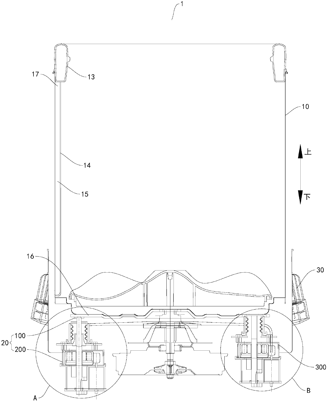
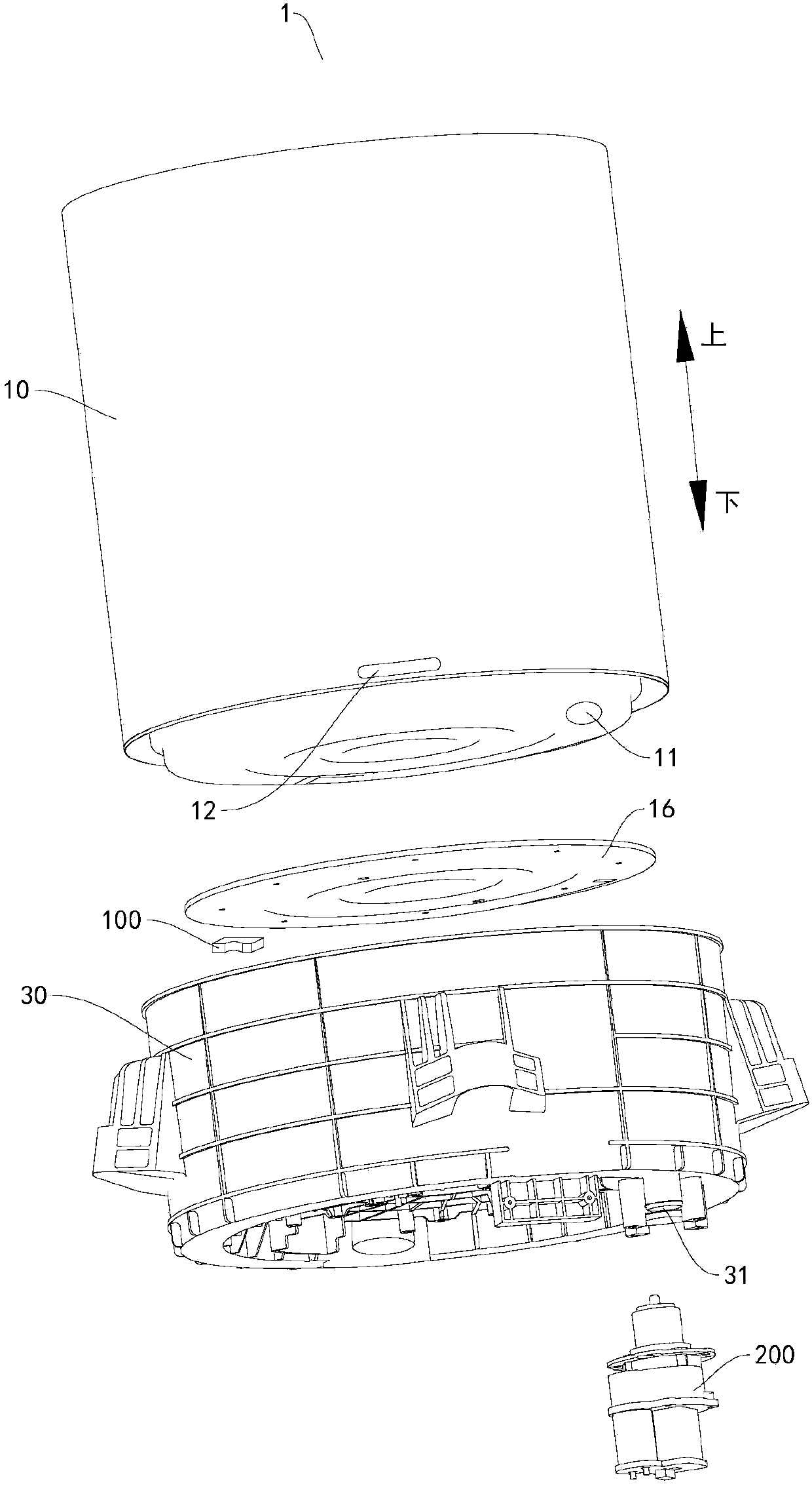
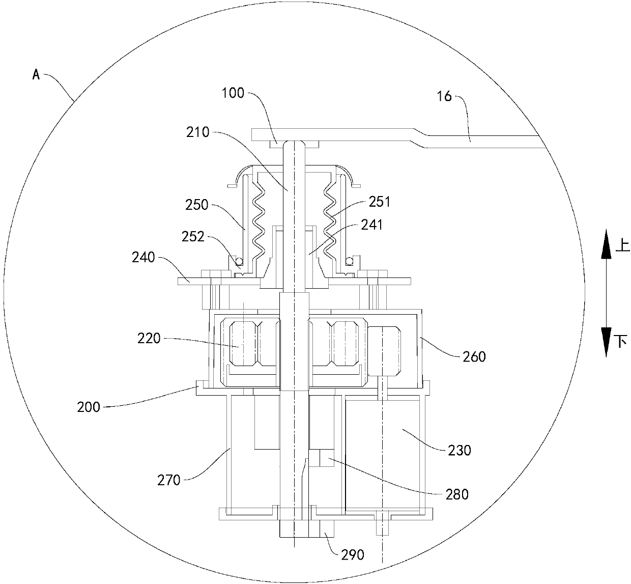
[0078] Embodiments of the present invention are described in detail below, examples of which are shown in the drawings, wherein the same or similar reference numerals designate the same or similar elements or elements having the same or similar functions throughout. The embodiments described below by referring to the figures are exemplary only for explaining the present invention and should not be construed as limiting the present invention.

[0079] In describing the present invention, it should be understood that the terms "upper", "lower", "inner", "outer", "clockwise", "counterclockwise", "axial", "radial", " The orientation or positional relationship indicated by "circumferential direction" is based on the orientation or positional relationship shown in the drawings, and is only for the convenience of describing the present invention and simplifying the description, rather than indicating or implying that the referred device or element must have a specific orientation, Co...


PUM


Abstract

The invention discloses a dehydrating barrel stopping mechanism used for a washing machine and the washing machine. The dehydrating barrel stopping mechanism used for the washing machine comprises a first stopping structure, a second stopping structure, a first gear set and a first driving device; the first stopping structure is suitable for being arranged on a dehydrating barrel of the washing machine, the second stopping structure comprises a stopping bar which can move between a stopping position and a releasing position, the stopping bar stops on the side of the first stopping structure along the periphery of the dehydrating barrel when in the stopping position and allows the first stopping structure to cross the stopping bar along the periphery of the dehydrating barrel when in the releasing position, the first gear set is in transmission connection with the stopping bar, the first driving device is in transmission connection with the first gear set and drives the stopping bar tomove between the stopping position and the releasing position through the first gear set. According to the dehydrating barrel stopping mechanism used for the washing machine, rotation of the dehydrating barrel can be stopped, and the stopping effect is stable and reliable.

Description

technical field [0001] The invention relates to the technical field of electric appliance manufacturing, in particular to a dehydration tub blocking mechanism for a washing machine and a washing machine with the dehydration tub blocking mechanism for a washing machine. Background technique [0002] Such as a pulsator-type washing machine, there are multiple dehydration holes on the surrounding wall of the dehydration bucket, and the dehydration bucket and the water tank are connected. The dehydration bucket is a clothes storage area for washing clothes. This part of the water does not participate in washing, and the water that really participates in washing is the part in the dehydration bucket, which causes a huge waste of water resources. In addition, too much water between the dehydration bucket and the water tank will also reduce the concentration of detergent and affect washing. Effect. In addition, during the washing process, the dehydration bucket is prone to counter...

Claims


Application Information

Patent Timeline
Patent Type & Authority Applications(China)
IPC IPC(8): D06F37/12D06F37/40
CPCD06F37/12D06F37/40
Inventor 李章京周薇杨姚
Owner WUXI LITTLE SWAN ELECTRIC CO LTD
Features
  • Generate Ideas
  • Intellectual Property
  • Life Sciences
  • Materials
  • Tech Scout
  • Unparalleled Data Quality
  • Higher Quality Content
  • 60% Fewer Hallucinations
Learn More