
Anti-whirl method

A technology of anti-rotation and production methods, applied in chemical instruments and methods, chemical/physical/physicochemical processes, chemical/physical processes, etc.

Inactive Publication Date: 2010-12-01
朱荣
View PDF2 Cites 0 Cited by
  • Summary
  • Abstract
  • Description
  • Claims
  • Application Information

AI Technical Summary

Problems solved by technology

[0006] Specifically, the present invention provides a method for anti-swirl flow. By installing an anti-swirl flow device at the outlet of the reactor, it solves the problems caused by excessive delivery volume or circulation volume and equipment size during the liquid transportation process of the container. Swirl

Method used


Image

  • Anti-whirl method
  • Anti-whirl method
  • Anti-whirl method

Examples


Embodiment Construction

[0020] In order to have a clearer understanding of the technical features, purposes and effects of the present invention, the specific implementation manners of the present invention will now be described with reference to the accompanying drawings. Wherein, the same parts adopt the same reference numerals.

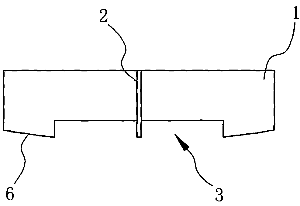
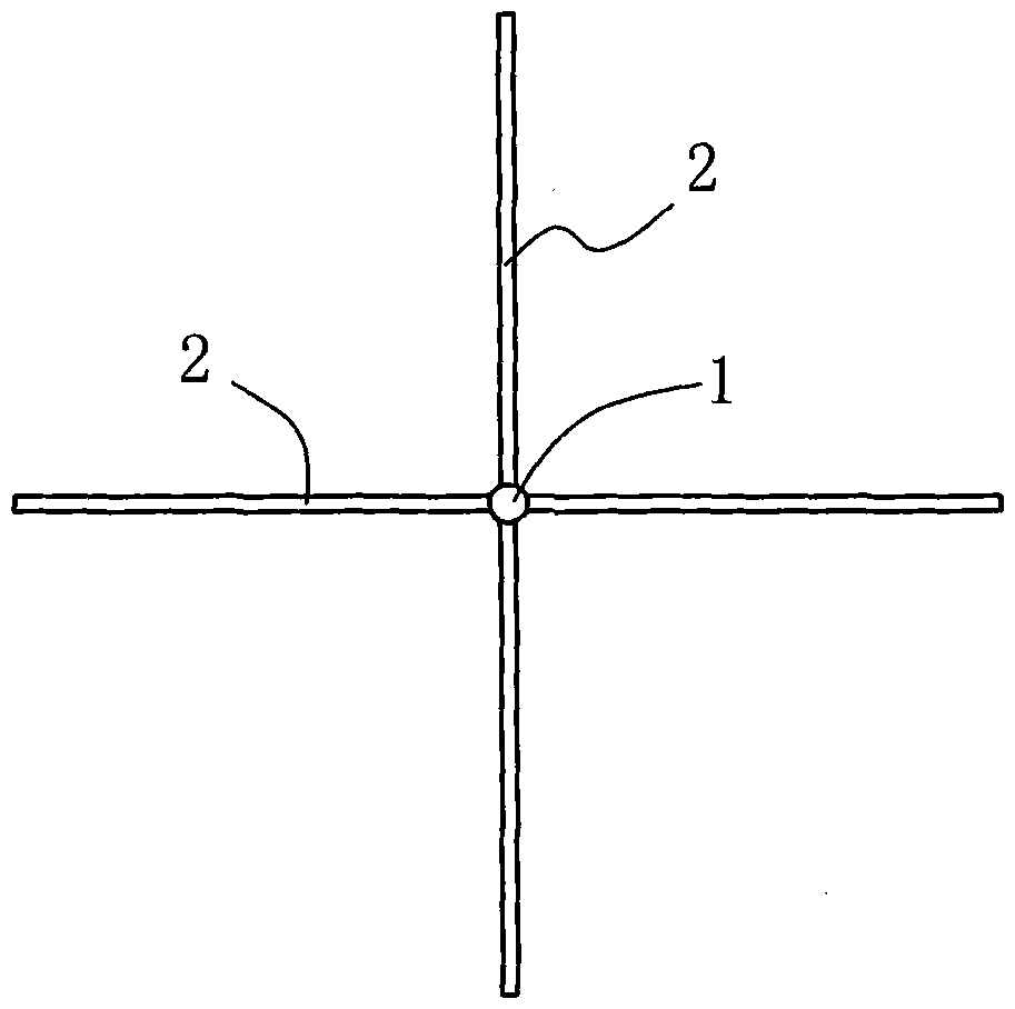
[0021] refer to figure 1 ,and figure 2 , in the anti-swirl method of the present invention, the preparation method of the anti-swirl device is as follows:

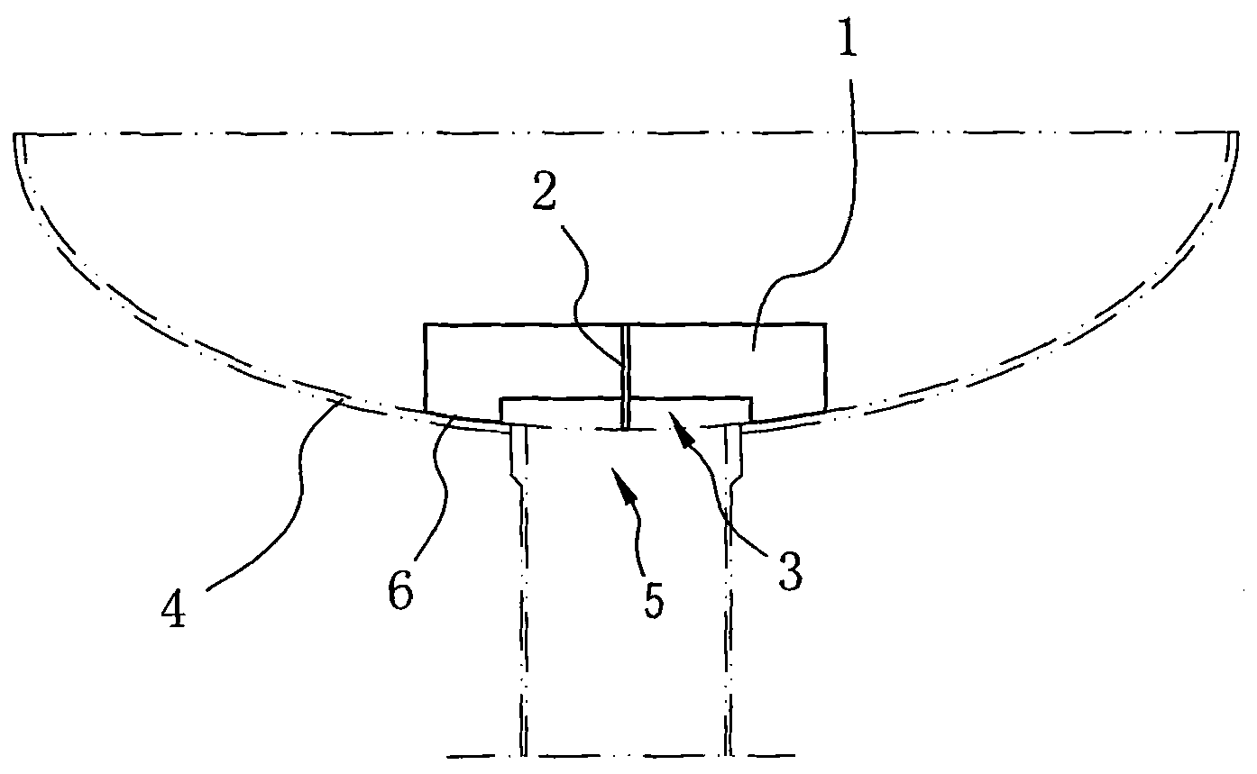
[0022] Each baffle plate 1 is radially fixedly connected to the vertical shaft 2, the anti-swirl flow device is fixedly arranged at the outlet 5 of the reactor 4, and a middle gap 3 is set at the end of the baffle plate 1 near the outlet 5, and the middle The baffles on both sides of the notch 3 are near the kettle end 6 , so that the near kettle end 6 matches the shape of the inner wall of the reactor 4 .

[0023] The near kettle end of many block baffle plates 1 is made into the arc shape that matches with react...


PUM

PropertyMeasurementUnit
Heightaaaaaaaaaa

Abstract

The invention discloses an anti-whirl method. The method comprises the step of installing an anti-whirl device at the exit of a reactor, wherein the manufacturing method of the anti-whirl device comprises the following steps of: fixedly connecting each baffle to an upright shaft in a radial form, fixedly arranging the anti-whirl device at the exit of the reactor, forming a middle gap at one end of each baffle close to the exit, wherein the baffles on the two sides of the middle gap are kettle near ends; and making the shape of the kettle near ends matched with that of the inner wall of the reactor. The method avoids the whirl phenomenon in a container caused by overlarge conveying capacity or circulation, the size of equipment and the like during fluid delivery.

Description

technical field [0001] The invention relates to a method for preventing swirl flow, in particular to a method for preventing swirl flow at the outlet of a chemical reactor, and a manufacturing method for an anti-swirl flow device. Background technique [0002] Reactor is an important equipment in petrochemical and fine chemical industry, and its main function is to complete the corresponding chemical reaction in the equipment. Whether the reactor is used as a reaction device, a storage device or an intermediate device, it involves the process of liquid transportation, that is, the process of transferring the materials in it to other facilities. If the material flow rate in the reactor is too fast or the liquid level is low, swirling flow may occur; especially the material outlet of the reactor is generally small, resulting in a sudden change in the flow area, which will inevitably generate vortex flow. [0003] The swirling phenomenon brings the following adverse effects to...

Claims


Application Information

Patent Timeline
IPC IPC(8): B01J19/00
Inventor 朱荣
Owner 朱荣
Features
  • Generate Ideas
  • Intellectual Property
  • Life Sciences
  • Materials
  • Tech Scout
  • Unparalleled Data Quality
  • Higher Quality Content
  • 60% Fewer Hallucinations
Learn More