Acoustic micropump

a micro-pump and acoustic technology, applied in the field of micro-pump, can solve the problems of valve leakage of pump type and other problems

Inactive Publication Date: 2000-01-04
THE BOARD OF TRUSTEES OF THE LELAND STANFORD JUNIOR UNIV
View PDF6 Cites 220 Cited by
  • Summary
  • Abstract
  • Description
  • Claims
  • Application Information

AI Technical Summary

Benefits of technology

It is another object to provide a micropump

Problems solved by technology

This type of pump also su

Method used


Image

  • Acoustic micropump
  • Acoustic micropump
  • Acoustic micropump

Examples


Embodiment Construction

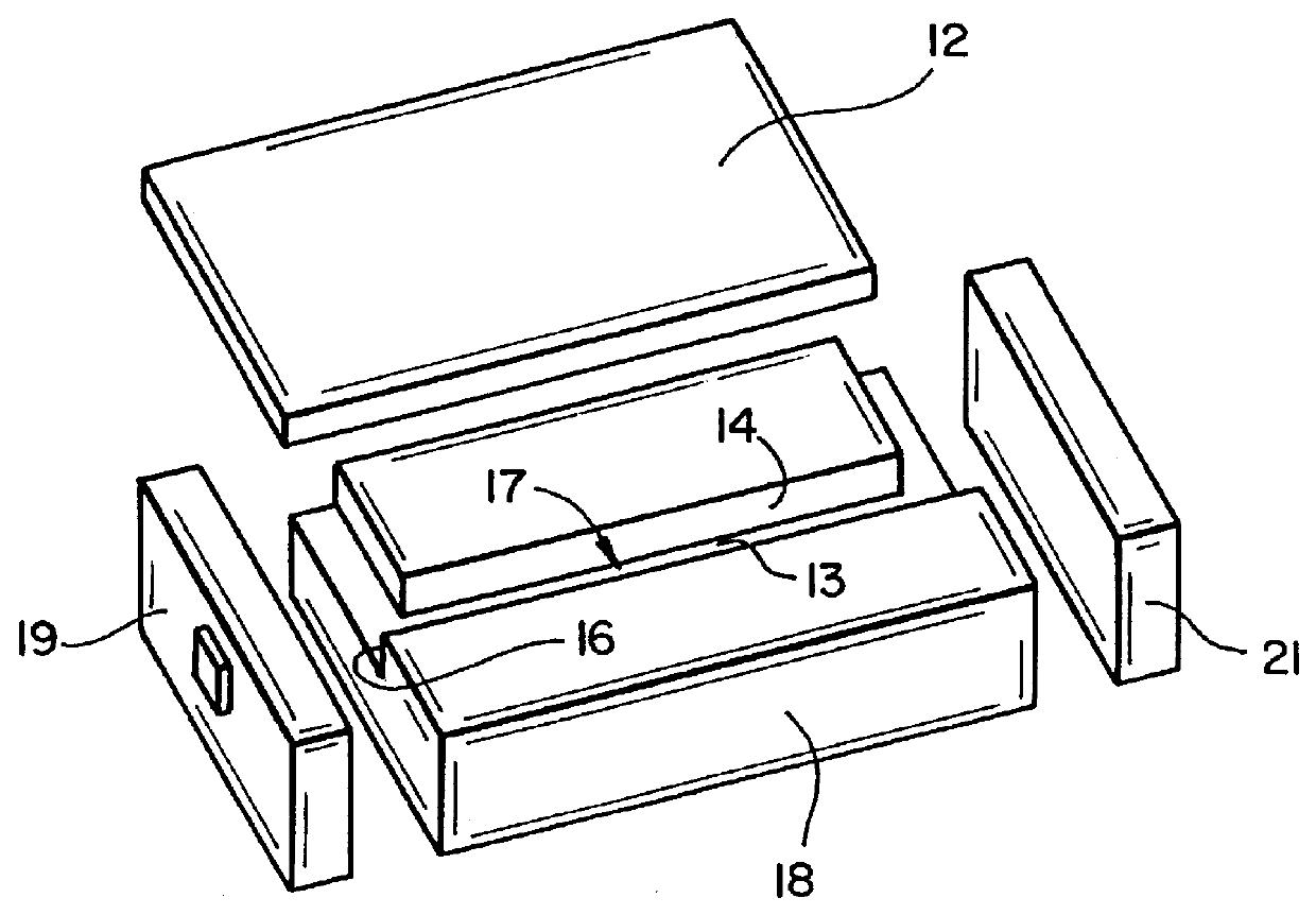
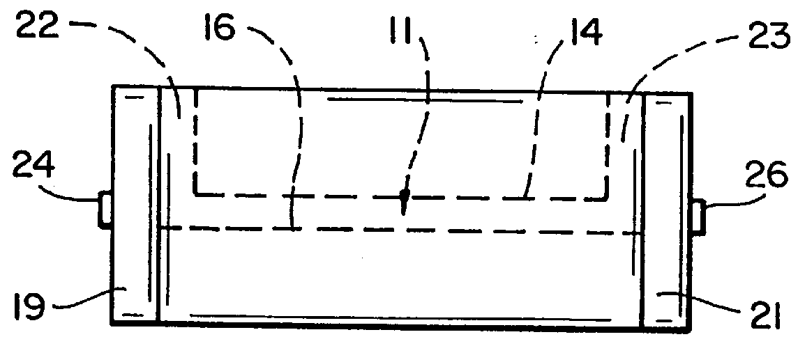
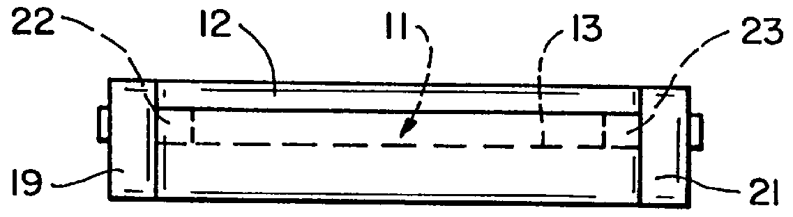
In accordance with this invention, fluid is caused to flow along a microchannel by the interaction between a longitudinal acoustic wave and the fluid being pumped. More particularly, the fluid is impelled by an acoustic pressure gradient which can arise from streaming and / or radiation pressure. These effects are difficult to separate in an acoustic micropump in which fluids are pumped by longitudinal acoustic waves traveling along a microchannel. Streaming requires attenuation to occur, while radiation pressure is present at interfaces between media of different acoustic impedances. Radiation pressure can also be induced by causing a gradient in pressure either by a change of the intensity or the velocity of the wave. Classical examples of radiation pressure involve sound waves in one medium incident on an interface with another medium. This causes a reflection of the sound and a difference in intensity across the interface. The resulting pressure difference causes mound formation o...


PUM


Abstract

A micropump in which a fluid is pumped by the interaction of longitudinal acoustic waves and the fluid in the microchannel. The micropump having an acoustical transducer responsive to a high-frequency input and directing a longitudinal acoustic wave into the channel which induces a pressure gradient. The fluid in the channel flowing in the direction of travel of the acoustic wave in the channel.

Description

This invention relates generally to an acoustic micropump and, more particularly, to microfabricated fluid pumps in which the fluid is caused to flow by interaction between a longitudinal acoustic wave and the fluid.High accuracy fluid pumps having flow rates on the order of microliters per minute (.mu.l / min) which can be fabricated by micromachining techniques have gained interest in the last few years. Applications for micropumps include small dosage in-vivo drug release, on-chip cooling systems, integrated chemical analysis systems, chemical processing, and mixing.Prior art microfabricated pumps have included flexible diaphragm valves working peristaltically and flexible diaphragm valved electrothermopneumatic liquid pumps. The flow of liquid in such pumps is pulsating. This type of pump also suffers from valve leakage. There is a need for a micropump which has no moving parts in which the fluid flow can be electronically controlled.This invention uses longitudinal acoustic waves...

Claims


Application Information

Patent Timeline
IPC IPC(8): B01L3/00F04F7/00F04B19/00
CPCB01L3/50273F04B19/006F04F7/00B01L2400/0436Y10S366/04
Inventor HALLER, MATTHEW ISAACKHURI-YAKUB, BUTRUS THOMAS
Owner THE BOARD OF TRUSTEES OF THE LELAND STANFORD JUNIOR UNIV
Why Eureka
Try Eureka