Lifting sling

a sling and sling body technology, applied in the field of rigging, can solve the problems of not being easily adjustable on the job site, adjusting the sling length, and not being able to adjust the sling, so as to reduce abrasion and rapid wear, reduce abrasion, and prevent abrasion and rapid wear

Active Publication Date: 2008-07-15
VERSABAR
View PDF9 Cites 210 Cited by
  • Summary
  • Abstract
  • Description
  • Claims
  • Application Information

AI Technical Summary

Benefits of technology

[0019]A polyurethane spring cut sleeve or tube also serves as a flexible thimble at the “bite” or eye of the sling to prevent abrasion and rapid wear at these critical points.
[0020]A polyurethane spiral cut or spring-cut clear cover can also be used over the entire length of the sling that is otherwise not covered as a flexible protective cover, minimizing abrasion and keeping the sling intact.
[0021]The present invention features an insert that is preferably of straight fiber filler (preferably liquid crystal

Problems solved by technology

One of the problems with slings and grommets of either metallic or plastic construction is that of field adjusting the sling length.
Wire rope slings are not adjustable.
Plastic and polymeric slings are typically se

Method used


Image

  • Lifting sling
  • Lifting sling
  • Lifting sling

Examples


Embodiment Construction

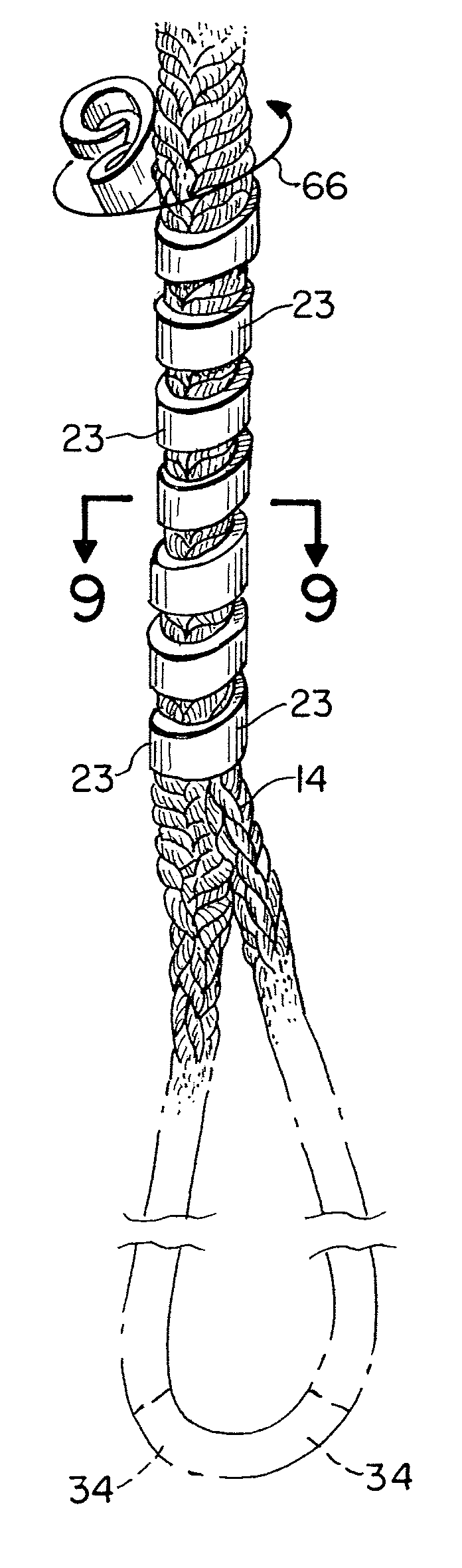
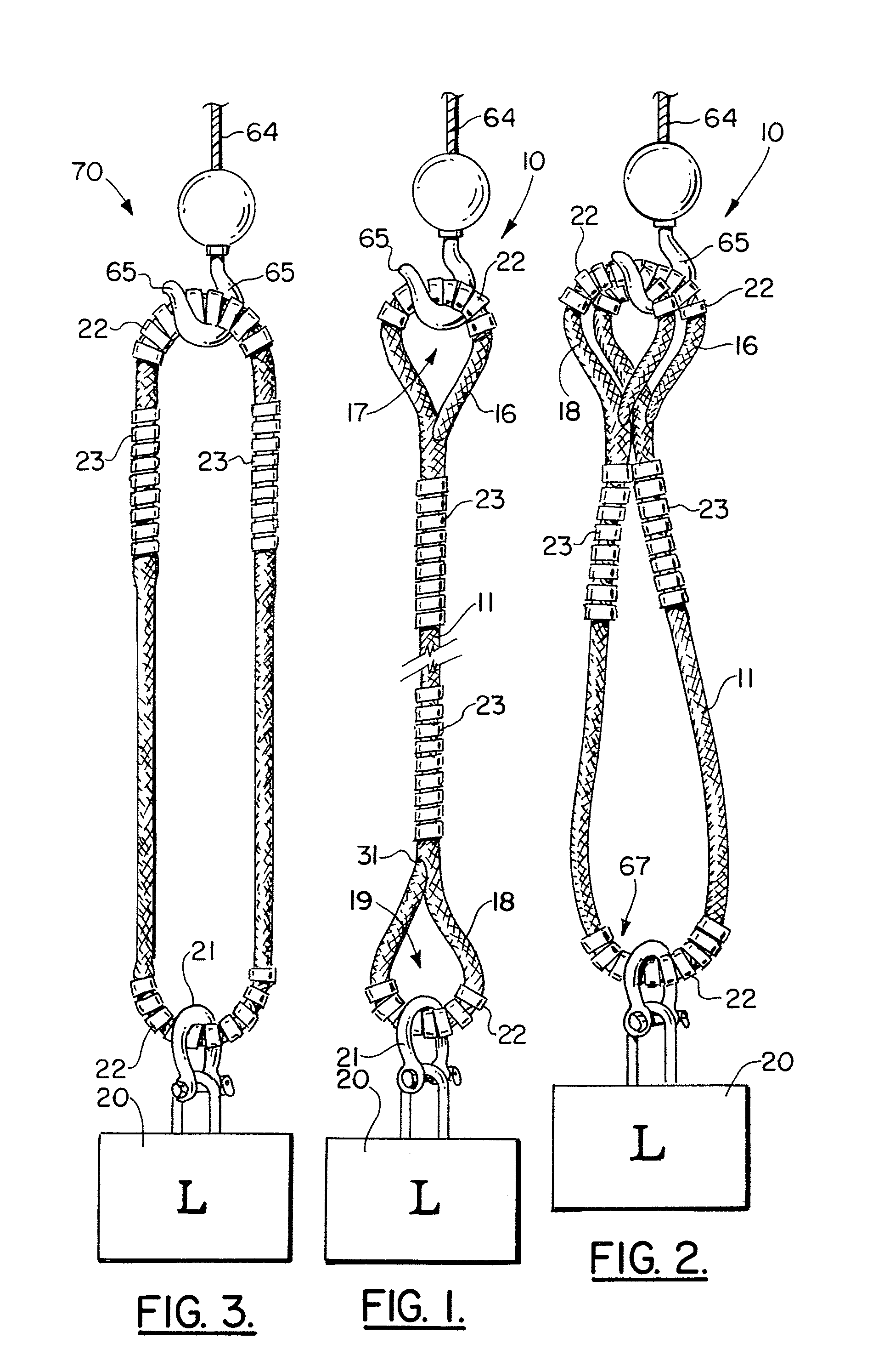
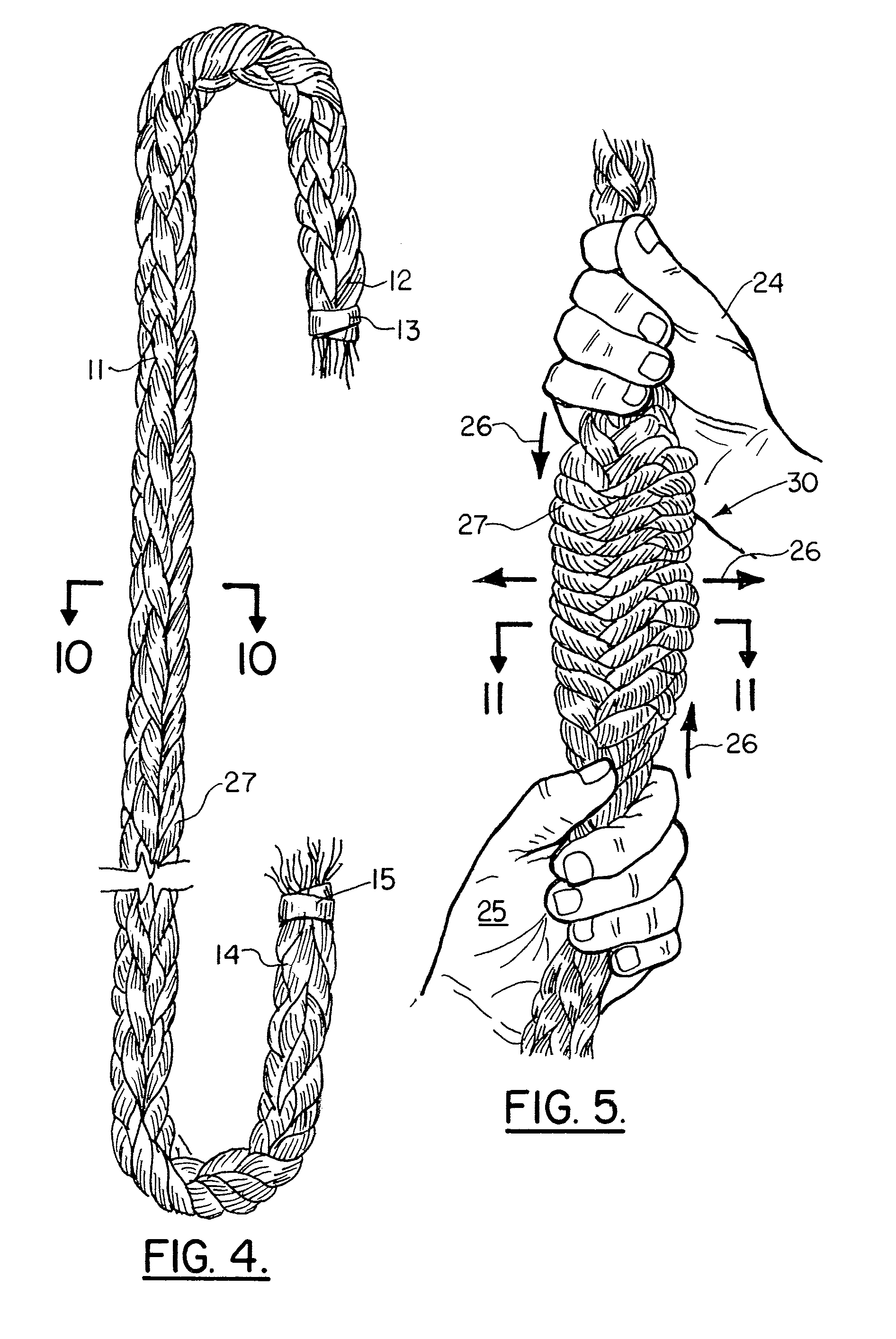
[0048]FIGS. 1 and 2 show generally the preferred embodiment of the apparatus of the present invention designated generally by the numeral 10. Lifting sling 10 includes a sling member 11 (preferably polymeric, more preferably liquid crystal polymer) that can be provided with a pair of spaced apart lifting eyes 16, 18 as shown in FIGS. 1 and 2.

[0049]In FIG. 2, the sling member 11 is much longer and is doubled so that both of the lifting eyes 16, 18 are positioned in side by side relationship and supported by hook 65 attached to crane lifting line 64. In FIG. 1, a single strand configuration for sling 10 is shown with the lifting eye 16 being attached to hook 65. The lower lifting eye 18 is attached to shackle 21 which is affixed to both lifting eye 18 and load 20 to be lifted.

[0050]Lifting eye 16 provides an opening 17 that enables it to be attached to hook 65 of a crane and its lifting line 64. Similarly, eye 18 has an opening 19 that enables it to be attached to an object to be lift...


PUM


Abstract

A lifting sling and a lifting grommet are disclosed which can be fabricated of a high tensile strength polymeric material, preferably a woven polymer such as liquid crystal polymer fibers, that are woven in a rope or cable configuration. The apparatus features an elongated woven material length of cable that is spliced. Plastic, preferably polyurethane spring cut tube sleeves are positioned as a grip on the splices to allow for handling in the field without concern for the splice becoming disassembled or undone. The sling and grommet of the present invention can each be provided with a clear cover spring cut tube that serves as a flexible protective cover for minimizing abrasion and maintaining the slings appearance.

Description

CROSS-REFERENCE TO RELATED APPLICATIONS[0001]Priority of U.S. Provisional Patent Application Ser. No. 60 / 470,695, filed May 15, 2003, incorporated herein by reference, is hereby claimed.STATEMENT REGARDING FEDERALLY SPONSORED RESEARCH OR DEVELOPMENT[0002]Not applicableREFERENCE TO A “MICROFICHE APPENDIX”[0003]Not applicableBACKGROUND OF THE INVENTION[0004]1. Field of the Invention[0005]The present invention relates to rigging, namely slings and grommets that are used during heavy lifting and more particularly to a heavy lifting system that includes a specially configured sling and grommet of improved construction wherein an elongated sling member includes an elongated woven portion having first and second ends and a central passageway surrounded by the woven material, and wherein one or more flexible sleeves can be optionally fitted to the elongated sling member at its loop portions and at its connecting portions. If the tensile material is one large circular loop, it is referred to...

Claims


Application Information

Patent Timeline
IPC IPC(8): B66C1/12
CPCB66C1/12D07B1/185D07B1/18D07B2401/2075
Inventor KHACHATURIAN, JON E.
Owner VERSABAR
Why Eureka
Try Eureka