
Anti-swirling method

A technology of anti-rotation and production methods, applied in chemical instruments and methods, chemical/physical/physicochemical processes, chemical/physical processes, etc.

Active Publication Date: 2012-02-08
SHANGHAI TAIJIE CHEM
View PDF5 Cites 0 Cited by
  • Summary
  • Abstract
  • Description
  • Claims
  • Application Information

AI Technical Summary

Problems solved by technology

[0005] The invention provides a method for anti-swirl flow. By installing an anti-swirl flow plate at the outlet of the reactor, it solves the problem of the container in the process of liquid transportation due to the excessive delivery volume or circulation volume, and the size of the equipment. swirl phenomenon

Method used


Image

  • Anti-swirling method
  • Anti-swirling method
  • Anti-swirling method

Examples


Embodiment Construction

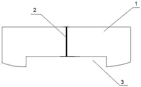
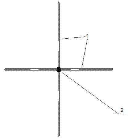
[0019] refer to figure 1 ,and figure 2 , in the anti-swirl method of the present invention, the preparation method of the anti-swirl plate is as follows:

[0020] Connect one end of each baffle plate 1 to different directions of the same vertical shaft 2, and make it radially arranged vertically; one end of the baffle plate 1 connected to the vertical shaft 2 forms a fixed end, and the other end forms a near kettle end.

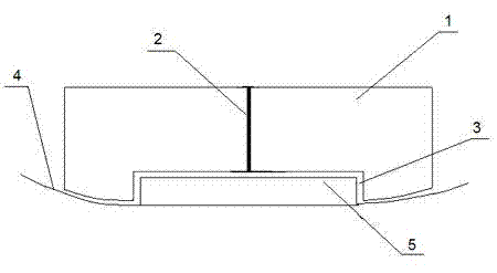
[0021] Make the end near the reactor of multiple baffles into an arc shape that matches the inner wall 4 of the reactor, and make the lower side of the baffle 1 higher than the bottom end of the arc near the end of the reactor to form a gap between the bottom side of the baffle 1 and the outlet of the reactor. 5 to match the notch 3.

[0022] The number and height of the baffles 1 can be adjusted according to the volume of the reactor, wherein the number of baffles is preferably 3-16, and the height of the baffles is preferably 5-200 cm.

[0023] refer to...


PUM


Abstract

The invention relates to an anti-swirling method. The anti-swirling method is that an anti-swirling plate is arranged on the outlet of a reactor. A manufacturing method of the anti-swirling plate is that one-side ends of baffle plates are connected to a same vertical shaft at different directions, so the baffle plates are vertically arranged in a radial mode. The anti-swirling method allows a swirling phenomenon caused by reasons of large transmission capacity or circulation volume, equipment dimension and the like in the process of liquid transmission of a container to be solved.

Description

technical field [0001] The invention relates to a method for preventing swirl flow, in particular to a method for preventing swirl flow at the outlet of a chemical reactor, and a method for manufacturing an anti-swirl flow baffle. Background technique [0002] As the most common equipment in the field of production and storage, containers are widely used in chemical industry, new materials, water engineering and other fields. Whether the container is used as a reaction device, a storage device or an intermediate device, it will involve the liquid transfer process, that is, the process of transferring the liquid material in it to other facilities. If the flow rate of the material in the container is too fast or the liquid level is low, swirling flow may occur; especially the material outlet of the container is generally small, resulting in a sudden change in the flow area, which will inevitably generate vortex flow. [0003] The swirling phenomenon brings the following adver...

Claims


Application Information

Patent Timeline
Patent Type & Authority Applications(China)
IPC IPC(8): B01J19/00
Inventor 方剑
Owner SHANGHAI TAIJIE CHEM
Features
  • Generate Ideas
  • Intellectual Property
  • Life Sciences
  • Materials
  • Tech Scout
  • Unparalleled Data Quality
  • Higher Quality Content
  • 60% Fewer Hallucinations
Learn More