Electrothermal drive bistable state MEMS switch

An electrothermal drive, bistable technology, applied in the field of MEMS switches, can solve the problems of output nonlinearity, small driving force, long response time, etc., to reduce the hold signal, reduce system power consumption, and improve safety.

Inactive Publication Date: 2018-02-27
XI AN JIAOTONG UNIV
View PDF6 Cites 8 Cited by
  • Summary
  • Abstract
  • Description
  • Claims
  • Application Information

AI Technical Summary

Benefits of technology

This new technology uses pulsed voltages from an electric heater (V) type thermocouple that can be used instead of regular electrical current signals. By doing this, it saves energy while also reducing noise interference during operation compared to older methods like relays or solenoids. Additionally, by utilizing these techniques, there will be less risk of damage caused due to overheating. Overall, this innovation makes electronic devices safer without consuming too much battery life.

Problems solved by technology

This patented describes two technical problem addressed by this patents: how to improve the switching speed (switch) characteristics without sacrificing its reliability or efficiency over longer periods while also maintaining stable operation under various environmental conditions such as temperature changes.

Method used


Image

  • Electrothermal drive bistable state MEMS switch
  • Electrothermal drive bistable state MEMS switch
  • Electrothermal drive bistable state MEMS switch

Examples


Embodiment Construction

[0022] The present invention will be further described below in conjunction with the accompanying drawings.

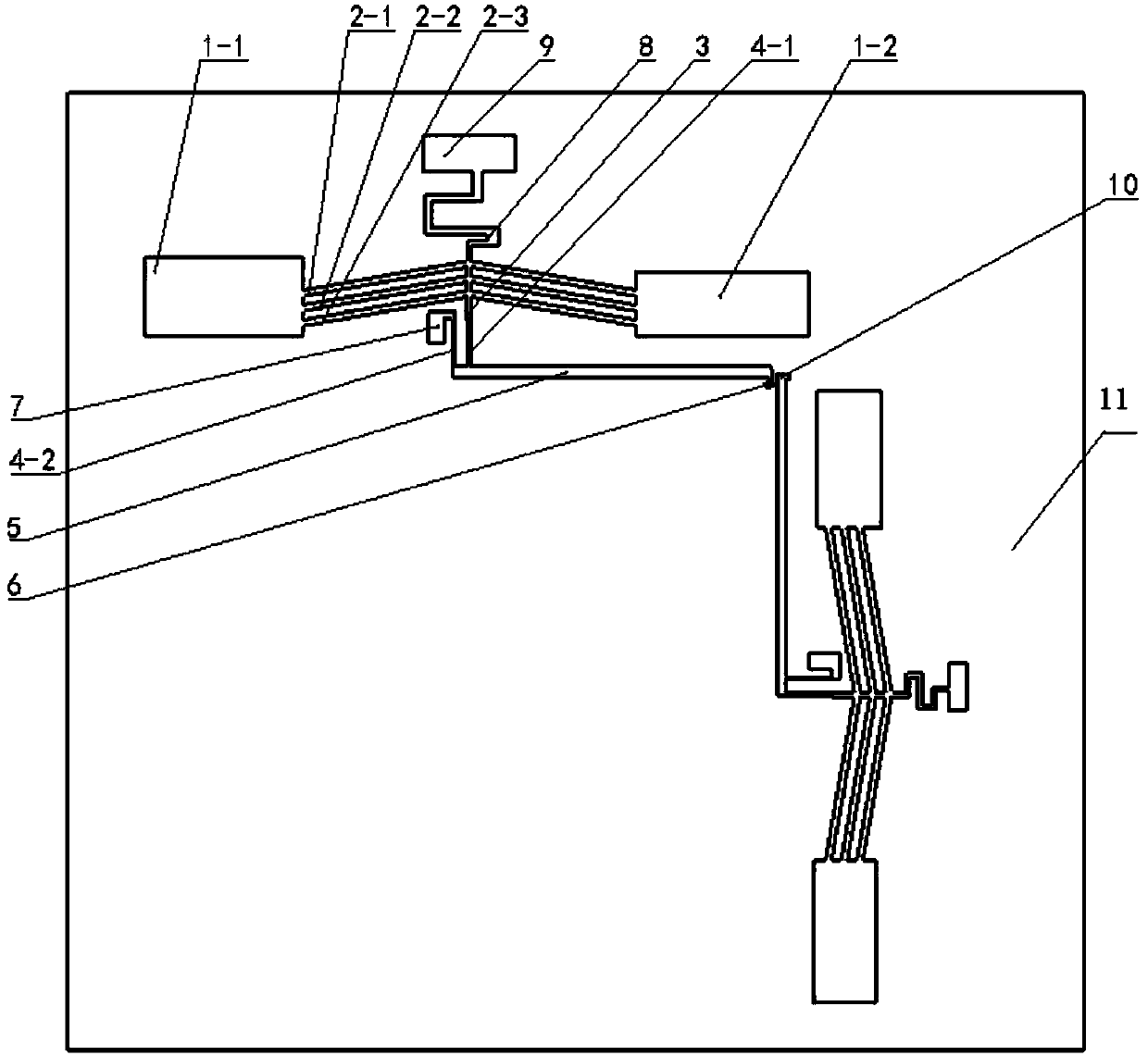
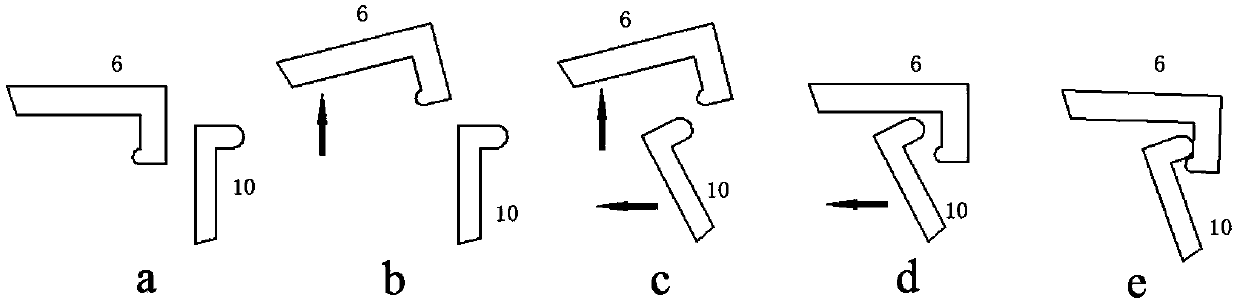
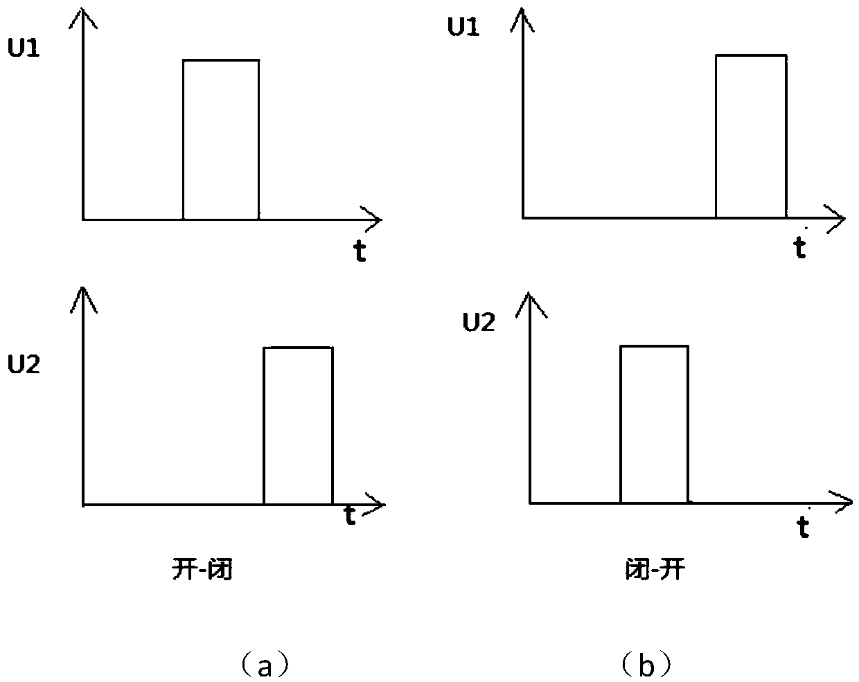
[0023] refer to figure 1 , an electrothermally driven bistable MEMS switch, comprising a square base 11, V-type electrothermal actuators I and V-type electrothermal actuators II are vertically distributed on the square base 11, and the V-type electrothermal actuators I are controlled by a drive circuit U1 Drive the first hook-shaped contact 6, the V-type electrothermal actuator II drives the second hook-shaped contact 10 under the control of another drive circuit U2, the first hook-shaped contact 6 and the second hook-shaped contact 10 contact and conduct When the circuit is connected, the first hook-shaped contact 6 and the second hook-shaped contact 10 do not contact or disconnect the circuit. The driving circuit U1 and the driving circuit U2 are pulse voltages, and there is a phase difference between the driving circuit U1 and the driving circuit U2.

[0024] Descr...


PUM

PropertyMeasurementUnit
Widthaaaaaaaaaa

Abstract

An electrothermally driven bistable MEMS switch, comprising a square base on which V-shaped electrothermal actuators I and V-shaped electrothermal actuators II are vertically distributed, and the V-shaped electrothermal actuator I drives the first hook under the control of a drive circuit Type contact, V-type electrothermal actuator II drives the second hook-type contact under the control of another drive circuit, the first hook-type contact and the second hook-type contact contact to conduct the circuit, the first hook-type contact The circuit is disconnected without contact with the second hook contact. The two drive circuits are pulse voltage and have a phase difference; using the thermoelectric effect and thermal expansion effect of the V-shaped beam, the hook is driven by applying voltage to cause thermal deformation. Contact movement; the invention has the advantages of high stability, large driving force, linear output, low power consumption and low cost.

Description


Claims


Application Information

Patent Timeline
Owner XI AN JIAOTONG UNIV
Why Eureka
Try Eureka