Safety warning device for dump truck unloading

A safety warning, dump truck technology, applied in signal devices, tilt-bearing vehicles, etc., can solve the problems of affecting the unloading efficiency, time-consuming and labor-intensive manual command, etc.

Active Publication Date: 2018-03-02
海门市知舟工业设计有限公司
View PDF5 Cites 4 Cited by
  • Summary
  • Abstract
  • Description
  • Claims
  • Application Information

AI Technical Summary

Problems solved by technology

[0005] In order to overcome the disadvantages that there is no special safety warning equipment at present, manual command is time-consuming and labor-intensive, and affects the unloading efficiency, the tech

Method used


Image

  • Safety warning device for dump truck unloading
  • Safety warning device for dump truck unloading
  • Safety warning device for dump truck unloading

Examples


Embodiment 1

[0036] A dump truck unloading safety warning device, such as Figure 1-8 As shown, it includes a bottom plate 1, a pole 2, a box body 3, a driving device 4 and a ringing device 5. The middle of the top of the bottom plate 1 is connected with a pole 2 by means of bolt connection, and the top of the pole 2 is connected with a box body. 3. A driving device 4 is provided at the inner bottom of the box body 3, and a bell device 5 is provided on the right side of the box body 3.

Embodiment 2

[0038] A dump truck unloading safety warning device, such as Figure 1-8 As shown, it includes a bottom plate 1, a pole 2, a box body 3, a driving device 4 and a ringing device 5. The middle of the top of the bottom plate 1 is connected with a pole 2 by means of bolt connection, and the top of the pole 2 is connected with a box body. 3. A driving device 4 is provided at the inner bottom of the box body 3, and a bell device 5 is provided on the right side of the box body 3.

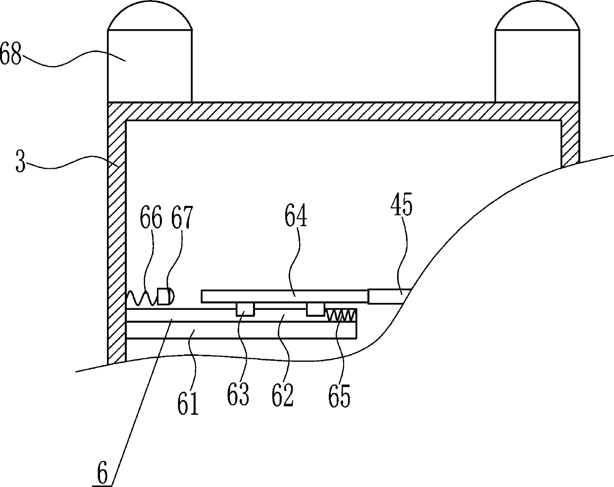
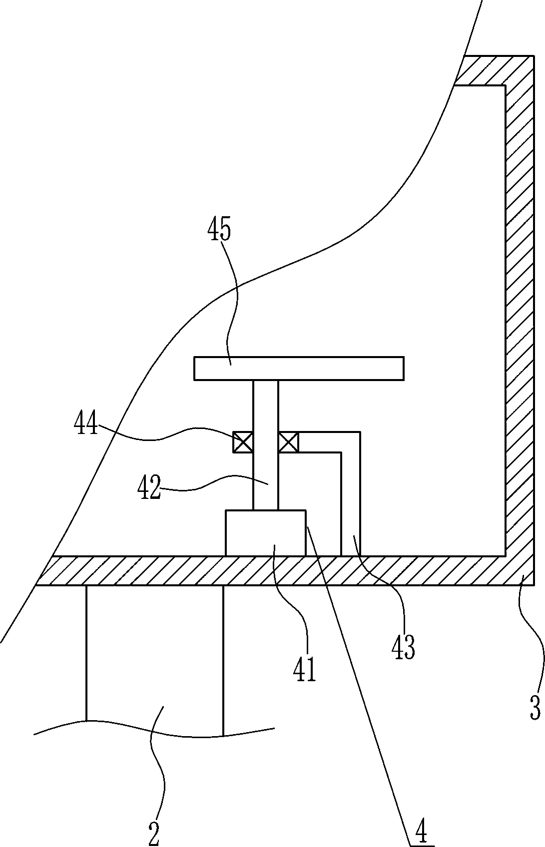
[0039] The driving device 4 includes a first motor 41, a first rotating shaft 42, a first L-shaped rod 43, a bearing seat 44 and a cam 45, and the middle of the inner top of the box body 3 is respectively connected with the first motor 41 and the first motor 41 by bolts. L-shaped bar 43, the first motor 41 is positioned at the left side of the first L-shaped bar 43, the output shaft of the first motor 41 is connected with the first rotating shaft 42 by coupling, the left end of the first L-shaped bar 43 is...

Embodiment 3

[0041] A dump truck unloading safety warning device, such as Figure 1-8 As shown, it includes a bottom plate 1, a pole 2, a box body 3, a driving device 4 and a ringing device 5. The middle of the top of the bottom plate 1 is connected with a pole 2 by means of bolt connection, and the top of the pole 2 is connected with a box body. 3. A driving device 4 is provided at the inner bottom of the box body 3, and a bell device 5 is provided on the right side of the box body 3.

[0042] The driving device 4 includes a first motor 41, a first rotating shaft 42, a first L-shaped rod 43, a bearing seat 44 and a cam 45, and the middle of the inner top of the box body 3 is respectively connected with the first motor 41 and the first motor 41 by bolts. L-shaped bar 43, the first motor 41 is positioned at the left side of the first L-shaped bar 43, the output shaft of the first motor 41 is connected with the first rotating shaft 42 by coupling, the left end of the first L-shaped bar 43 is...


PUM


Abstract

The invention relates to a warning device and especially relates to a safety warning device for dump truck unloading. The technical problem to be solved by the present invention is to provide a dump truck unloading safety warning device with good safety warning effect, time saving and labor saving, and improved unloading efficiency. To solve the above technical problem, the invention provides sucha safety warning device for dump truck unloading. The device comprises a base plate; a middle of the top of the base plate is connected with a strut in a bolt connection mode; a box body is connectedto a top of the strut; a drive device is arranged at a bottom of the box body; and a bell device is arranged on a right side of the box body. In the present invention, the bell device and a flashingdevice are driven by the drive device; the bell device emits a sound, the warning light is on and off, and the electric push rod drives the warning sign to swing, thereby effectively reminding peopleto pay attention to the safety of the warning and achieving the effect of a good security warning, saving time and effort, and improving the efficiency of discharge.

Description

technical field [0001] The invention relates to a warning device, in particular to a dump truck unloading safety warning device. Background technique [0002] A dump truck is a vehicle that unloads goods by itself through hydraulic or mechanical lifting. Also known as dump truck. It is composed of automobile chassis, hydraulic lifting mechanism, cargo compartment and power take-off device and other components. The compartment of a dump truck is divided into two types: backward tipping and sideways tipping. The movement of the piston rod is controlled by the operating system. Backward tipping is more common. [0003] When unloading a dump truck, if there are many people around, others need to direct it, otherwise it will affect the unloading efficiency and be unsafe. At present, there is no special safety warning equipment, and manual command is time-consuming and laborious, which affects the unloading efficiency. Therefore, it is urgent to develop a safety warning that is ...

Claims


Application Information

Patent Timeline
IPC IPC(8): B60Q9/00B60P1/04
Inventor 黄青娟冯宇婷魏芳萍其他发明人请求不公开姓名
Owner 海门市知舟工业设计有限公司
Why Eureka
Try Eureka