Laser marking device and marking method

A laser marking and laser marking machine technology, applied in laser welding equipment, welding equipment, metal processing equipment, etc., can solve the problem of low coding efficiency, and achieve the effect of ensuring the reading rate, ensuring stability, and good positioning

Active Publication Date: 2018-03-06
HANS LASER TECH IND GRP CO LTD
View PDF9 Cites 7 Cited by
  • Summary
  • Abstract
  • Description
  • Claims
  • Application Information

AI Technical Summary

Problems solved by technology

[0004] Laser marking two-dimensional codes requires good stability of the conveying equipment in order to ensure a high readability rate of the marked two-dimensional codes, and it is difficult for assembly line conveying dynamic coding equipment to meet the needs of round bottle cap products. Stable conveying when marking two-dimensional codes inside and outside at the same time; platform-type static coding equipment and beat-type station static coding equipment have low coding efficiency

Method used


Image

  • Laser marking device and marking method
  • Laser marking device and marking method
  • Laser marking device and marking method

Examples


Embodiment 1

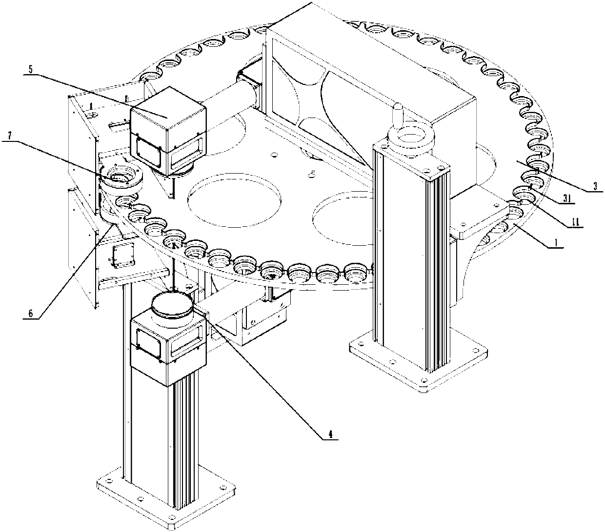
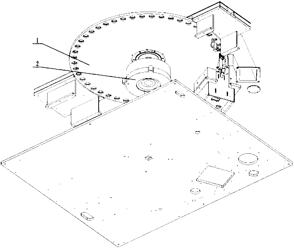
[0043] Such as Figure 1-2 As shown, the laser marking equipment provided by the present invention includes:

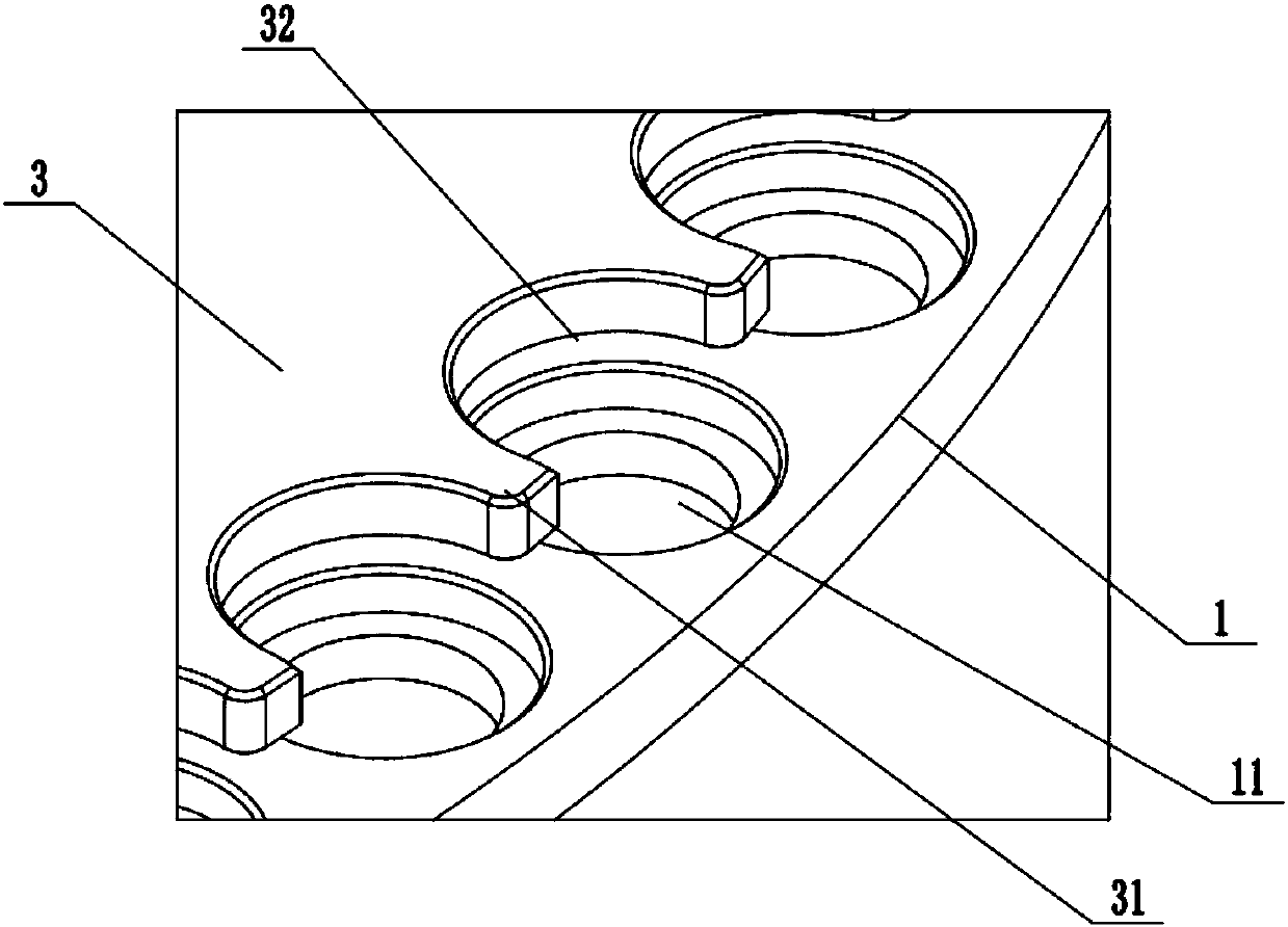
[0044] Circular turntable 1, and a plurality of positioning holes 11 for fixing products are radially arranged on the circular turntable 1; each positioning hole 11 can correspond to fix a product, such as bottle caps, etc.;

[0045] The drive assembly 2 is used to drive the circular turntable 1 to rotate at a constant speed; in this embodiment, the drive assembly 2 can be a DD motor, and at the same time, because the circular turntable 1 will continue to rotate during the marking process, it will generate The inertia of the laser will affect the trajectory of the laser marking, for example, it will cause the lines of the last printed two-dimensional code to bend. In the present invention, it has been proved by a lot of creative work that when the radius of the circular turntable 1 is R≧460mm (preferably 500mm), And when the rotational angular velocity ω≦22.5° / s (pre...

Embodiment 2

[0060] This embodiment provides a laser marking method, which includes the following steps:

[0061] S1. Set the marking parameters of the outer code and the inner code, and send them to the outer code laser marking machine and the inner code laser marking machine;

[0062] S2. Fixing the product into the positioning hole of the circular turntable, and the drive assembly drives the circular turntable to rotate at a constant speed;

[0063] S3. The outer code laser marking machine and the inner code laser marking machine simultaneously complete the code assignment on the outer surface and the inner surface of the product according to the marking parameters;

[0064] And S4, using the outer code reading unit and the inner code reading unit to simultaneously complete the decoding of the outer code and the inner code.


PUM

PropertyMeasurementUnit
radiusaaaaaaaaaa

Abstract

The invention discloses a laser marking device. The laser marking device comprises a circular rotary disc, a driving assembly, an outer code laser marking machine and an inner code laser marking machine, wherein a plurality of locating holes used for fixing products are formed in the circular rotary disc in the radial direction; the driving assembly is used for driving the circular rotary disc torotate at a constant speed; the outer code laser marking machine is arranged below the circular rotary disc, and is used for tagging the outer surfaces of the products to form outer codes; the inner code laser marking machine is arranged above the circular rotary disc, and is used for tagging the inner surfaces of the products to form inner codes; and the outer codes and the inner codes are formedat the same time. According to the laser marking device, dynamic tagging is achieved through a rotating workbench, stability of the bottle cap products during double-surface dynamic tagging can be guaranteed, time for waiting the products to be transported in place can be shorted, and production efficiency can be guaranteed to the greatest extent.

Description

technical field [0001] The invention relates to the field of packaging, in particular to a laser marking device and a marking method. Background technique [0002] At present, more and more product packaging surfaces on the market use laser technology to mark production dates, batch numbers, barcodes, QR codes, patterns, texts, etc., making them gradually replace traditional inkjet coding and mechanical embossing processes. [0003] However, for the two-sided marking of various bottle caps, laser printing two-dimensional code equipment commonly used in the market today includes: assembly line conveying dynamic coding equipment, platform static coding equipment, and beat-type (assembly line conveying or rotary table conveying) ) Station static coding equipment. There are obvious deficiencies in these several working methods: [0004] Laser marking two-dimensional codes requires good stability of the conveying equipment in order to ensure a high readability rate of the marke...

Claims


Application Information

Patent Timeline
Patent Type & Authority Applications(China)
IPC IPC(8): B23K26/362B23K26/08B41M5/24
CPCB23K26/0823B23K26/361B23K2101/007B41M5/24
Inventor 马泽清李绍军邓东朱剑辉韩永锋杨威欧阳江林高云峰
Owner HANS LASER TECH IND GRP CO LTD
Why Eureka
Try Eureka