Unlock instant, AI-driven research and patent intelligence for your innovation.
A high temperature compound regenerative adiabatic compressed air energy storage system
What is Al technical title?
Al technical title is built by PatSnap Al team. It summarizes the technical point description of the patent document.
A compressed air energy storage, high temperature technology, applied in the field of compressed air energy storage, to achieve high heat recovery efficiency, reduce costs, and reduce the effect of heat storage temperature difference
Active Publication Date: 2019-02-05
中盐华能储能科技有限公司
View PDF6 Cites 0 Cited by
Summary
Abstract
Description
Claims
Application Information
AI Technical Summary
This helps you quickly interpret patents by identifying the three key elements:
Problems solved by technology
Method used
Benefits of technology
Problems solved by technology
[0005] The purpose of the present invention is to provide a high-temperature compound regenerative adiabatic compressed air energy storage system to solve the problem of high-temperature heat storage and heat recovery in the existing adiabatic compressed air energy storage system, improve heat recovery efficiency, and reduce costs
Method used
Image
Click on the blue label to locate the original text in one second.
Reading with bidirectional positioning of images and text.
Examples
Embodiment 1
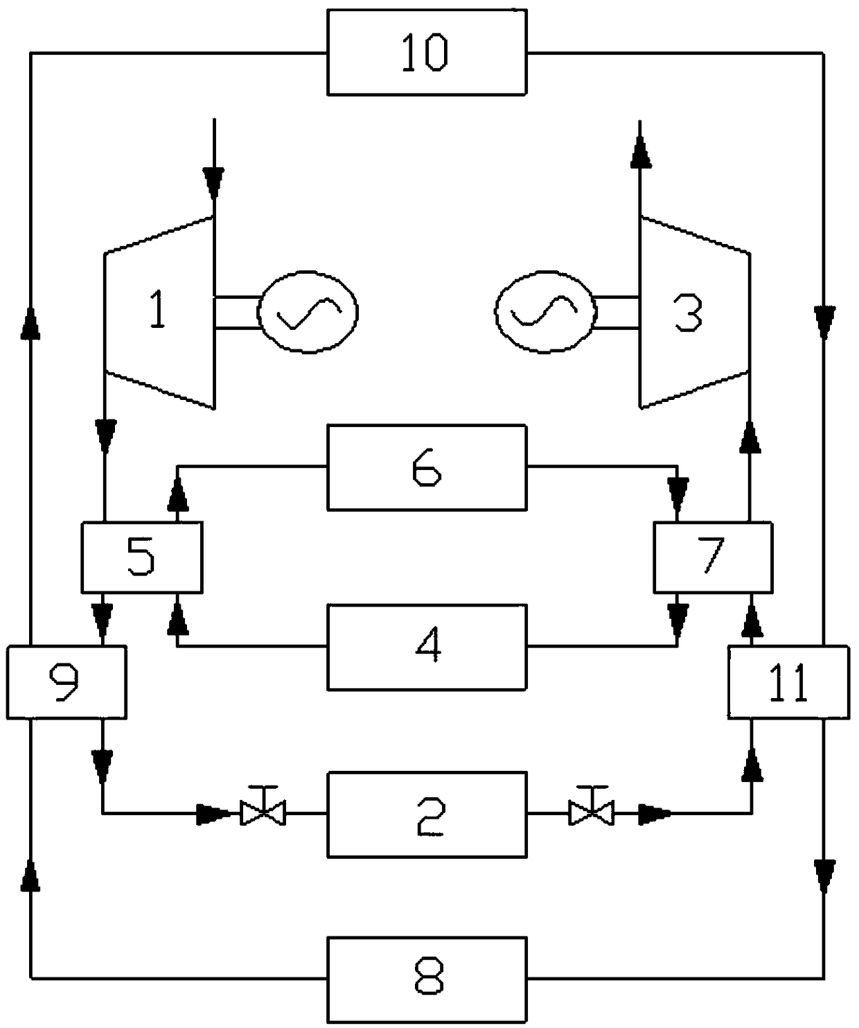
[0026] Such as figure 1 As shown, a single-stage compression, single-stage expansion high-temperature compound regenerative adiabatic compressed air energy storage system provided in this embodiment includes a high-temperature compressor unit 1, a gas storage chamber 2, a turbine generator unit 3, and a high-temperature regenerative cycle and medium temperature reheat cycle.
[0027] The high-temperature regenerative cycle includes a high-temperature cooler 5 , a high-temperature regenerator 6 , a high-temperature regenerator 7 and a high-temperature regenerator 4 . The heat exchange tube of the high-temperature cooler 5, the high-temperature regenerator 6, the heat-return tube of the high-temperature regenerator 7 and the high-temperature regenerator 4 are circularly connected;
[0028] The medium-temperature heat recovery cycle includes a medium-temperature cooler 9, a medium-temperature regenerator 10, a medium-temperature regenerator 11, and a medium-temperature regenerat...
Embodiment 2
[0043] This embodiment is basically the same as Embodiment 1. For the sake of brevity, in the description process of this embodiment, the same technical features as Embodiment 1 will not be described, and only the differences between this embodiment and Embodiment 1 will be described:
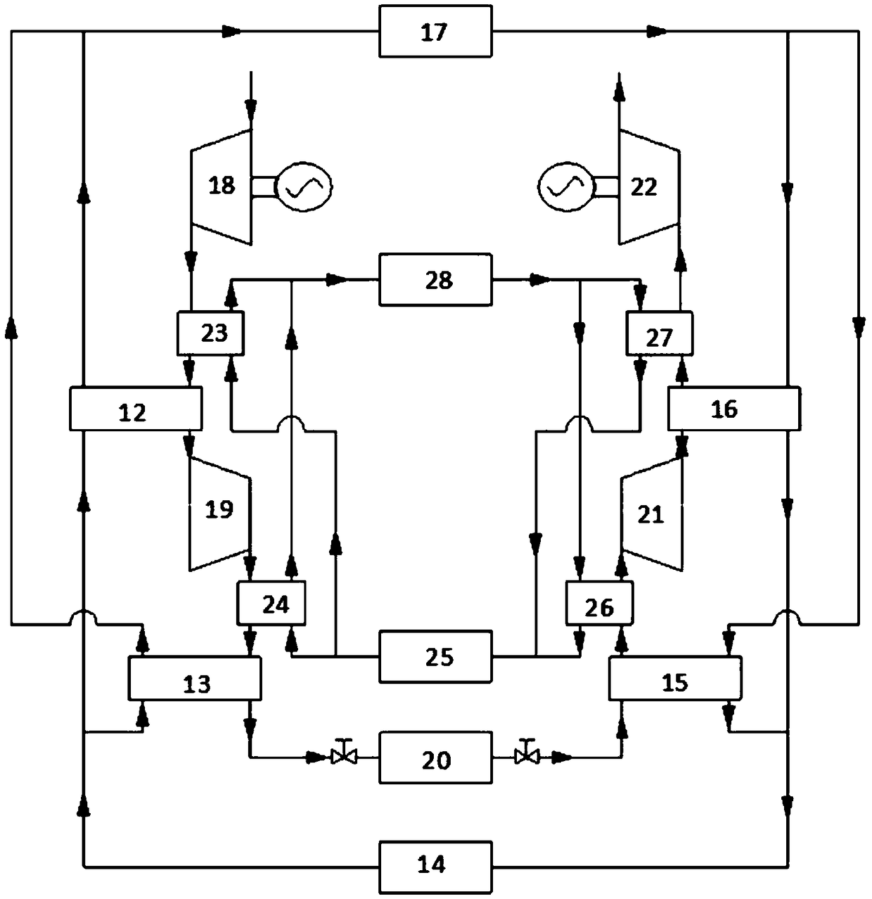
[0044] Such as figure 2 As shown, it is a dual-stage compression, dual-expansion high-temperature compound regenerative adiabatic compressed air energy storage system provided in this embodiment. Among them, the high-temperature compressor unit includes a multistage air compressor; the turbogenerator unit includes a multistage turboexpander and a generator.
[0045] In this embodiment, the high temperature compressor set includes a primary air compressor 18 and a secondary air compressor 19 ; the turbogenerator set includes a primary turbo expander 21 and a secondary turbo expander 22 .
[0046] The high-temperature cooler includes a first-level high-temperature cooler 23 and a second-level h...
PUM
Abstract
The invention provides a high-temperature duplex regeneration adiabatic compression air energy storage system. The system comprises a high-temperature compression unit, an air storage chamber, a turbine generator set, a high-temperature cooler, a high-temperature heat storer, a high-temperature regenerator, a high-temperature cold storer, a medium-temperature cooler, a medium-temperature heat storer, a medium-temperature regenerator and a medium-temperature cold storer; a heat exchange pipe of the high-temperature cooler, the high-temperature heat storer, a regeneration pipe of the high-temperature regenerator and the high-temperature cold storer are circularly connected; the heat exchange pipe of the medium-temperature cooler, the medium-temperature heat storer, a regeneration pipe of themedium-temperature regenerator and the medium-temperature cold storer are circularly connected; and the high-temperature compression unit, an intake pipe of the high-temperature cooler, an intake pipe of the medium-temperature cooler, the air storage chamber, an intake pipe of the medium-temperature regenerator, an intake pipe of the high-temperature regenerator and the turbine generator set areconnected in sequence. The gradient recovery and the duplex regeneration are performed on compression set by using high-temperature regeneration circulation and medium-temperature regeneration circulation, so that the heat storage temperature and the regeneration efficiency are improved; the heat storage temperature difference and the cost relative to single heat storage medium are reduced; and the temperature control is stable.
Description
technical field [0001] The invention relates to the technical field of compressed air energy storage, in particular to a high-temperature compound regenerative heat-insulation compressed air energy storage system. Background technique [0002] Compressed air energy storage technology uses air as an energy storage medium to store low-peak power or renewable energy grid-connected limited power. The traditional compressed air energy storage system uses an air compressor to compress the air into the air storage chamber for storage. When power generation is required, the high-pressure air is released to be mixed with fossil fuels for combustion, and the mixed products after combustion are used to drive the turbo expander to do work and drive power generation. machine output power. Due to the need to burn fossil fuels, there are certain restrictions on the system, and considering the current energy strategy and environmental protection requirements, an adiabatic compressed air en...
Claims
Application Information
Patent Timeline
Application Date:The date an application was filed.
Publication Date:The date a patent or application was officially published.
First Publication Date:The earliest publication date of a patent with the same application number.
Issue Date:Publication date of the patent grant document.
PCT Entry Date:The Entry date of PCT National Phase.
Estimated Expiry Date:The statutory expiry date of a patent right according to the Patent Law, and it is the longest term of protection that the patent right can achieve without the termination of the patent right due to other reasons(Term extension factor has been taken into account ).
Invalid Date:Actual expiry date is based on effective date or publication date of legal transaction data of invalid patent.

