Improved low temperature heat pipe heat exchanger

A heat pipe heat exchanger, an improved technology, applied to indirect heat exchangers, lighting and heating equipment, etc., can solve the problems of wasting heat energy, polluting fresh air, and low heat exchange efficiency, so as to improve heat recovery efficiency and reduce energy The effect of improving the consumption and heat transfer coefficient

Inactive Publication Date: 2007-11-14
北京德天节能设备有限公司
View PDF1 Cites 9 Cited by
  • Summary
  • Abstract
  • Description
  • Claims
  • Application Information

AI Technical Summary

Problems solved by technology

When centralized air conditioners and industrial drying equipment perform heat exchange work, a large amount of heat energy will be removed, which not only wastes heat energy, but also brings thermal pollution to the environment. With the continuous improvement of people's living standards and the vigorous development of industry, this The problem is becoming more and more serious. In order to recycle the energy contained in central air conditioners and industrial drying equipment, various heat exchangers using the principle of heat exchange are constantly appearing in this technical field to try to solve this problem, but the heat exchangers of the prior art Due to low heat exchange efficiency, high manufacturing and use costs, it has not been vigorously promoted and applied. The gas-gas heat exchangers in the prior art are generally divided into rotary heat exchangers, plate heat exchangers and heat pipe heat exchangers. The heat recovery efficiency of the wheel heat exchanger is relatively high. The disadvantage is that due to the rotation of the wheel core, each part of the wheel is alternately exposed to the fresh air and the exhaust air. Explosive dust and gas, and other harmful substances) will be adsorbed in the wheel core when in contact, and when this part of the wheel core is turned to the fresh air side due to the rotation of the wheel, bacteria, stench, explosive dust and gas, and other harmful substances are transferred to the fresh air, polluting the fresh air; at the same time, the moisture adsorbed in the wheel core will freeze when encountering cold fresh air to damage the runner; in addition, the wheel is a rotating part, and the seal is not tight enough, so it is inevitable that the exhaust air will be harmful. The material leaks to the side where the fresh air is sucked in. In addition, there are disadvantages of high maintenance costs, power requirements, and high prices; the plate heat exchanger dissipates heat through multi-layer heat sinks, and the exhaust air is directly transferred by metal plates, so the heat recovery efficiency is not as good as The rotary heat exchanger is high, but at the same time, it has the disadvantages of high maintenance cost, high price, large volume, large resistance loss and low heat recovery efficiency; while the heat pipe heat exchanger, although the heat recovery efficiency is slightly lower than the rotary heat exchanger , but higher than the plate heat exchanger, and because the heat pipe heat exchanger is heat transfer by the liquid working fluid in the tube, there is no cross-contamination, the new and exhaust rooms are strictly sealed, and flow in their respective air channels without mutual leakage It is relatively hygienic and safe to freeze with fresh air. However, the current general-purpose low-temperature heat pipe heat exchanger still has the problems of complicated manufacturing process, high cost and low heat recovery efficiency. The device discloses a heat 
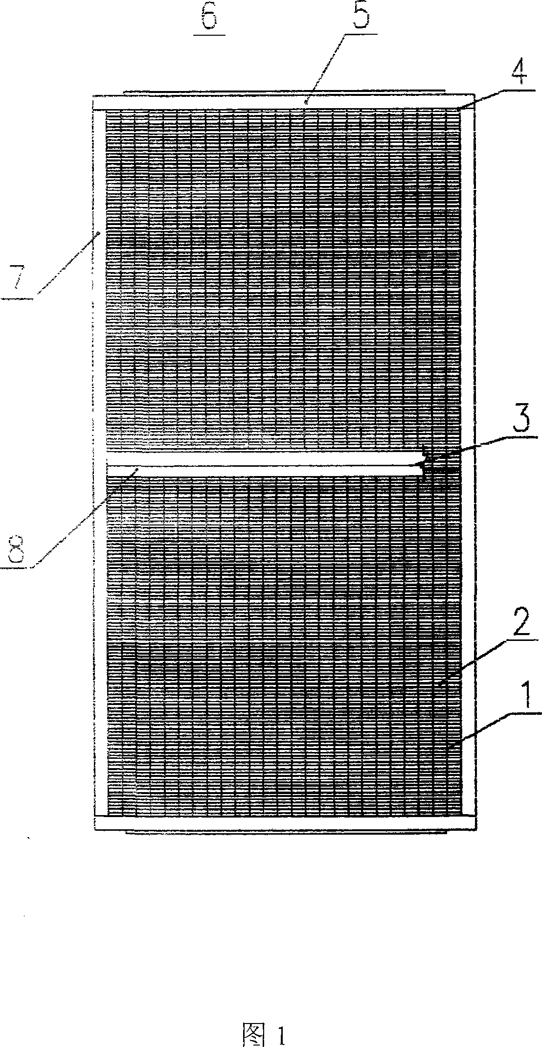
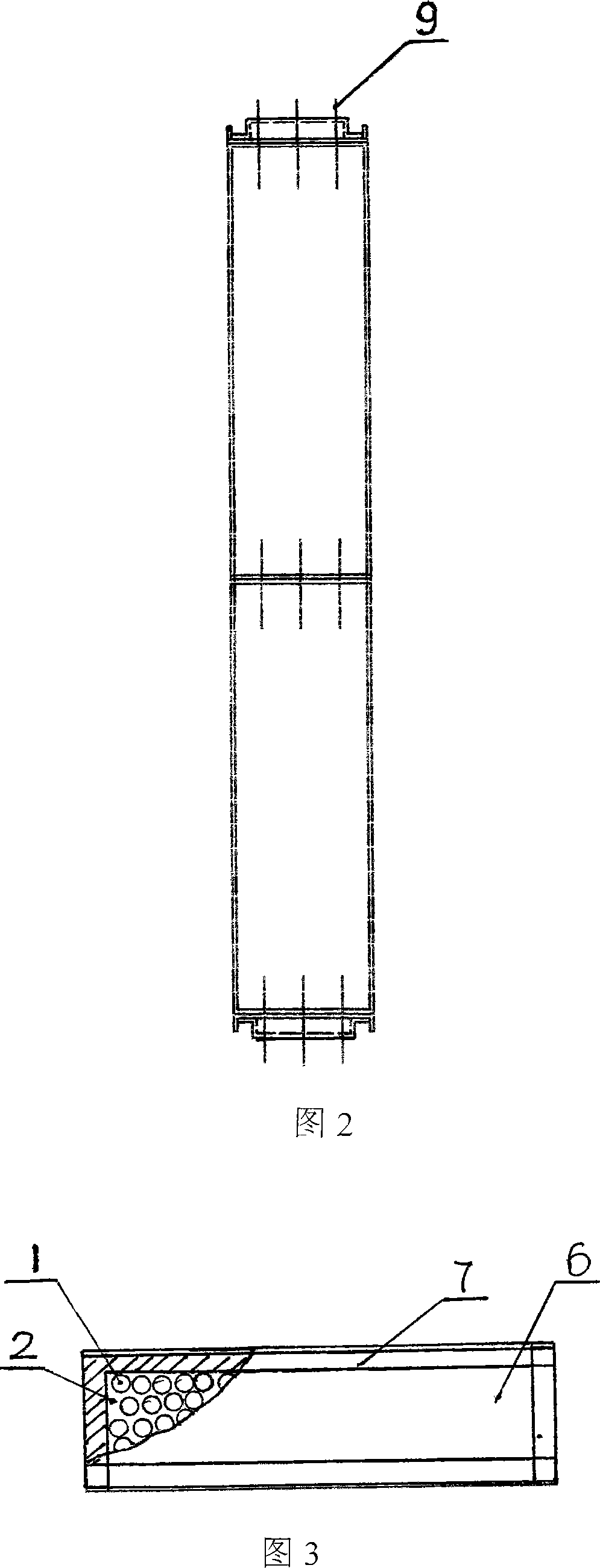
pipe heat exchanger, which is a single heat pipe element made by rolling an aluminum tube with extended cooling fins on the outside of the tube and multiple heat-absorbing grooves on the inner wall. The side triangles are arranged in bundles and installed in the frame shell. The tubes are filled with liquid working fluid. Each heat pipe element is separated by a middle partition to form two areas of fresh air and exhaust air to realize heat exchange. Due to the heat dissipation of the rolled aluminum tube outer wall The area of ​​the fins is not large, so there must be gaps between the rows and columns, so that the heat dissipation area is reduced, the fins cannot increase the ripples, and the heat recovery efficiency is low. During manufacture, each tube needs to be vacuumed, vacuum baked and filled with liquid, which cannot be completed. Batch production, high manufacturing costs, these shortcomings limit the popularization and application of low-temperature heat pipe heat exchangers, how to improve the shortcomings of existing low-temperature heat pipe heat exchangers, improve heat recovery efficiency, simplify the manufacturing process, reduce manufacturing and use costs, and facilitate promotion Application is an urgent problem to be solved in this field

Method used


Image

  • Improved low temperature heat pipe heat exchanger
  • Improved low temperature heat pipe heat exchanger

Examples


Embodiment Construction

[0017] The present invention will be further described below in conjunction with the accompanying drawings. As can be seen from Fig. 1-Fig. , end plate 4, side frame 5, cover plate 6, upper and lower frame 7, connecting plate 8 and fastening bolt 9, and multiple rectangular aluminum plate fins 2 are superimposed into a rectangular cube form with gaps, in the middle of the rectangular cube An aluminum middle partition 3 is set, and the distance between the fins 2 of each aluminum plate is 3 millimeters. There are a plurality of regularly arranged through holes corresponding to the aluminum fins 2 and the aluminum middle partition 3, and the hole distance is 50 millimeters. The hollow aluminum tube 1 is inserted into the through hole, and the hollow aluminum tube 1 is expanded by the tube expanding machine to form a tight fit with the multi-piece rectangular aluminum fins 2 and the aluminum partition 3, and the end plates 4 corresponding to the through holes are matched at both e...


PUM


Abstract

The invention discloses a second generation low temperature heat pipe and its making craft way , composing of aluminum tube, aluminum plate fin, aluminum clapboard ,frame ,endplate ,cover plate ,yoke plate and fastening bolt, many rectangle alumna plate fin overlap to rectangle cubic type with inner clearance with center spacer set in the central part, on the aluminum plate fin and alumina clapboard has many regular spread turned-over edge pylomes, and alumina tubes inbesinsert in the pylomes, the aluminum tube tightly fit to the aluminum fin and alumina after extends by expanding tube machine. The two ends of aluminum tube are seal weld, and ammonia or acetone liquid is filled in the aluminum tube, forming entire aluminum heat tube's heat exchanging subject, fix the heat exchanging subject to the inner shell composed by frame, endplavte, cover plate, yoke plate through fastening bolts. The clapboard divides the inner shell space into tow sealed areas of air intaking and discharging air. In this invention, the heat exchanger's volume is small, the making craft is simple ,low cost, reducing the environment's heat pollution.

Description

Technical field: [0001] The invention relates to the technical field of low-temperature heat pipes in heat conduction technology, in particular to an improved low-temperature heat pipe heat exchanger. Background technique: [0002] As we all know, central air-conditioning facilities are equipped in various buildings where people live, work and study, such as large-scale commercial buildings, office buildings, hotels, workshops, etc., and industrial drying equipment is also widely used in various industrial fields. Centralized air-conditioning The role of air conditioning is to maintain a fresh indoor living or working environment, and it is necessary to remove harmful substances produced in living activities and production operations and introduce fresh outdoor air. Industrial drying equipment should also remove the hot and humid air after drying, and introduce heated dry air outside to supplement. When centralized air conditioners and industrial drying equipment perform he...

Claims


Application Information

Patent Timeline
Patent Type & Authority Applications(China)
IPC IPC(8): F28D15/02
Inventor 王诗英王礼华
Owner 北京德天节能设备有限公司
Why Eureka
Try Eureka