Waste heat recovery for condensing type anti-corrosive gas/oil-fired boiler

A waste heat recovery system and oil-fired boiler technology, applied in damage protection, heat exchange equipment, indirect heat exchangers, etc., can solve problems affecting the service life of heat exchangers, acid corrosion of heat exchanger walls, and ineffective recycling. , to achieve the effect of improving heat recovery efficiency, less maintenance cost, and simple assembly

Active Publication Date: 2012-04-11
SHANDONG TIANLI DRYING TECH & EQUIP
View PDF10 Cites 9 Cited by
  • Summary
  • Abstract
  • Description
  • Claims
  • Application Information

AI Technical Summary

Problems solved by technology

The exhaust gas temperature of gas boilers is generally 120-250°C, and 7%-15% of the sensible heat and 11% of the latent heat in the flue gas are directly discharged into the atmosphere without being utilized, which not only causes a lot of energy waste but also exacerbates the thermal pollution of the environment
In order to make full use of energy and recover the physical heat energy of the flue gas, the waste heat recovery of the flue gas is often carried out by reducing the exhaust gas temperature, and when the wall temperature of the heat exchanger is lower than the dew point temperature of the flue gas, the water vapor in the flue gas It will be condensed, and this process can recover a large amount of latent heat of water vapor. At the same time, the acid gas contained in the flue gas forms a weak acid solution, which is easy to cause acid corrosion on the wall of the heat exchanger. Therefore, in order to prevent the corrosion of the heat exchanger, the boiler smoke Gas waste heat is generally discharged to the atmosphere above the dew point temperature, that is, only a part of the sensible heat is recovered, and the latent heat is basically not effectively recovered. This is the root cause of the low recovery rate of gas / oil-fired boiler flue gas waste heat
Some Chinese patent application documents (such as 200420049576, 200910048782, 200910238452, 2009102617842, 201010225079X) mentioned the recovery of boiler flue gas latent heat, but did not consider the corrosion of weakly acidic condensed water on the heat exchanger body, which will seriously affect the heat exchanger service life, the overall economic benefit is not obvious

Method used


Image

  • Waste heat recovery for condensing type anti-corrosive gas/oil-fired boiler
  • Waste heat recovery for condensing type anti-corrosive gas/oil-fired boiler

Examples


Embodiment Construction

[0027] The present invention will be further described below in conjunction with the accompanying drawings and embodiments.

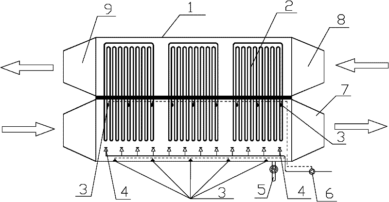
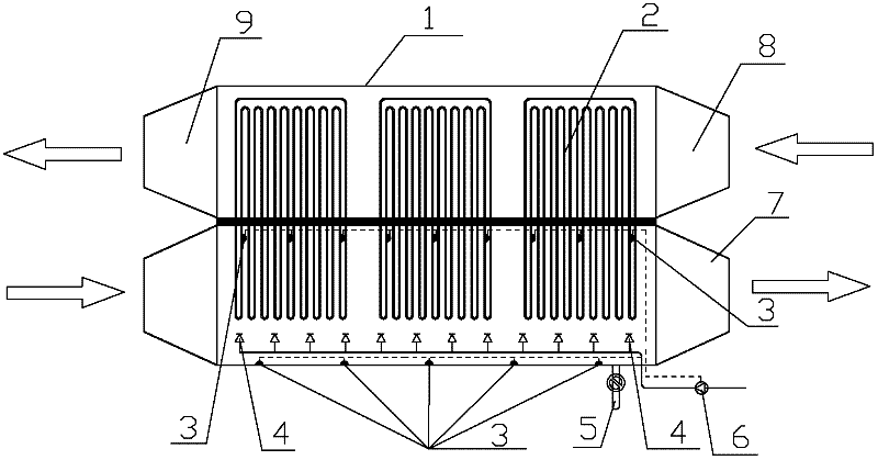
[0028] figure 1 Among them, a waste heat recovery system for a condensing anti-corrosion gas / oil-fired boiler, which includes a heat exchanger body and a solution spraying device partially arranged in the heat exchanger body, the flue gas side of the heat exchanger body One end is connected to the exhaust port of the gas / oil-fired boiler to receive the high-temperature flue gas from the oil-fired / gas-fired boiler; the other end is provided with a low-temperature flue gas exhaust port 7, and the other end of the heat exchanger body is provided with an air or water inlet 8 , the other end is the heated air or water outlet 9 connected to the heat user.

[0029] The heat pipe heat exchanger body 1 and the solution spraying device work together. The heat exchanger body 1 is assembled from a shell and a heat pipe bundle 2 (oscillating flow heat pipe or grav...


PUM


Abstract

The invention discloses a waste heat recovery for condensing type anti-corrosive gas/oil-fired boiler, which can effectively recover the physical heat of boiler flue; not only lots of sensible heat is recovered, but also the latent heat of vaporization discharged by condensation of water vapor. The structure is as follows: a common heat tube heat exchanger body and a solution spraying device are included. The heat tube heat exchanger body is used for transferring the heat from the flue side to the other side by the shock transmission of the heat tube, so as to heat the air or water; the solution sprayed by the sprayer is uniformly distributed in the heat exchange tube on the flue side and on the inner wall of the heat exchanger, so as to remove the corrosion from the weakly acidic solution formed by condensation of water vapor in the flue of the boiler.

Description

technical field [0001] The invention relates to a waste heat recovery system, in particular to a waste heat recovery system capable of recovering sensible heat and latent heat of steam gasification of gas / oil-fired boiler flue gas and preventing the heat exchanger body from being corroded by weakly acidic gas. Background technique [0002] Natural gas or fuel oil contains a considerable amount of hydrogen, and the amount of water vapor produced by combustion is large. Among them, the water vapor volume composition in the flue gas of gas-fired boilers is generally 15%-19%, and the water vapor volume composition in the flue gas produced by oil-fired boilers 10%-12%. The exhaust gas temperature of gas boilers is generally 120-250°C, and 7%-15% of the sensible heat and 11% of the latent heat in the flue gas are directly discharged into the atmosphere without being utilized, which not only causes a lot of energy waste but also exacerbates the thermal pollution of the environment...

Claims


Application Information

Patent Timeline
Patent Type & Authority Applications(China)
IPC IPC(8): F23J15/00F28D15/02F28F19/00
Inventor 耿文广李选友高玲马晓旭员冬玲
Owner SHANDONG TIANLI DRYING TECH & EQUIP
Why Eureka
Try Eureka