
Motion kinetic energy conversion and storage device

A kinetic energy conversion and storage device technology, used in engines, machines/engines, mechanisms that generate mechanical power, etc., can solve problems such as waste of inertial energy in acceleration and deceleration, and achieve the effect of ingenious structure, stable phase, and avoiding damage

Active Publication Date: 2018-03-06
泉州市艺家好家居装饰有限公司
View PDF4 Cites 2 Cited by
  • Summary
  • Abstract
  • Description
  • Claims
  • Application Information

AI Technical Summary

Problems solved by technology

[0004] In view of the above situation, in order to make up for the technical deficiencies existing in the prior art, the present invention provides a kinetic energy conversion and storage device to solve the problem of waste of inertial energy in the process of speeding up and decelerating the car and bumping or shaking

Method used


Image

  • Motion kinetic energy conversion and storage device
  • Motion kinetic energy conversion and storage device
  • Motion kinetic energy conversion and storage device

Examples


Embodiment Construction

[0014] The specific implementation manners of the present invention will be described in further detail below in conjunction with the accompanying drawings.

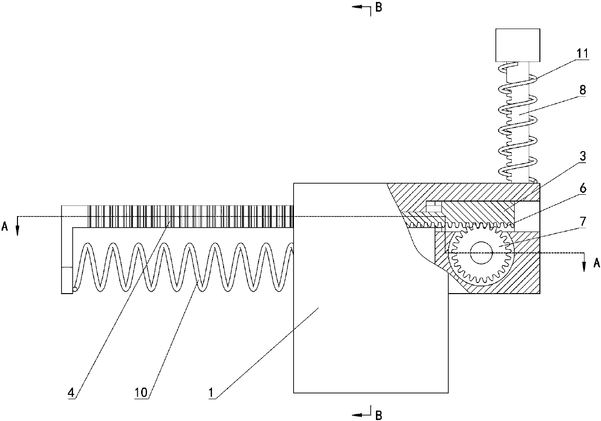
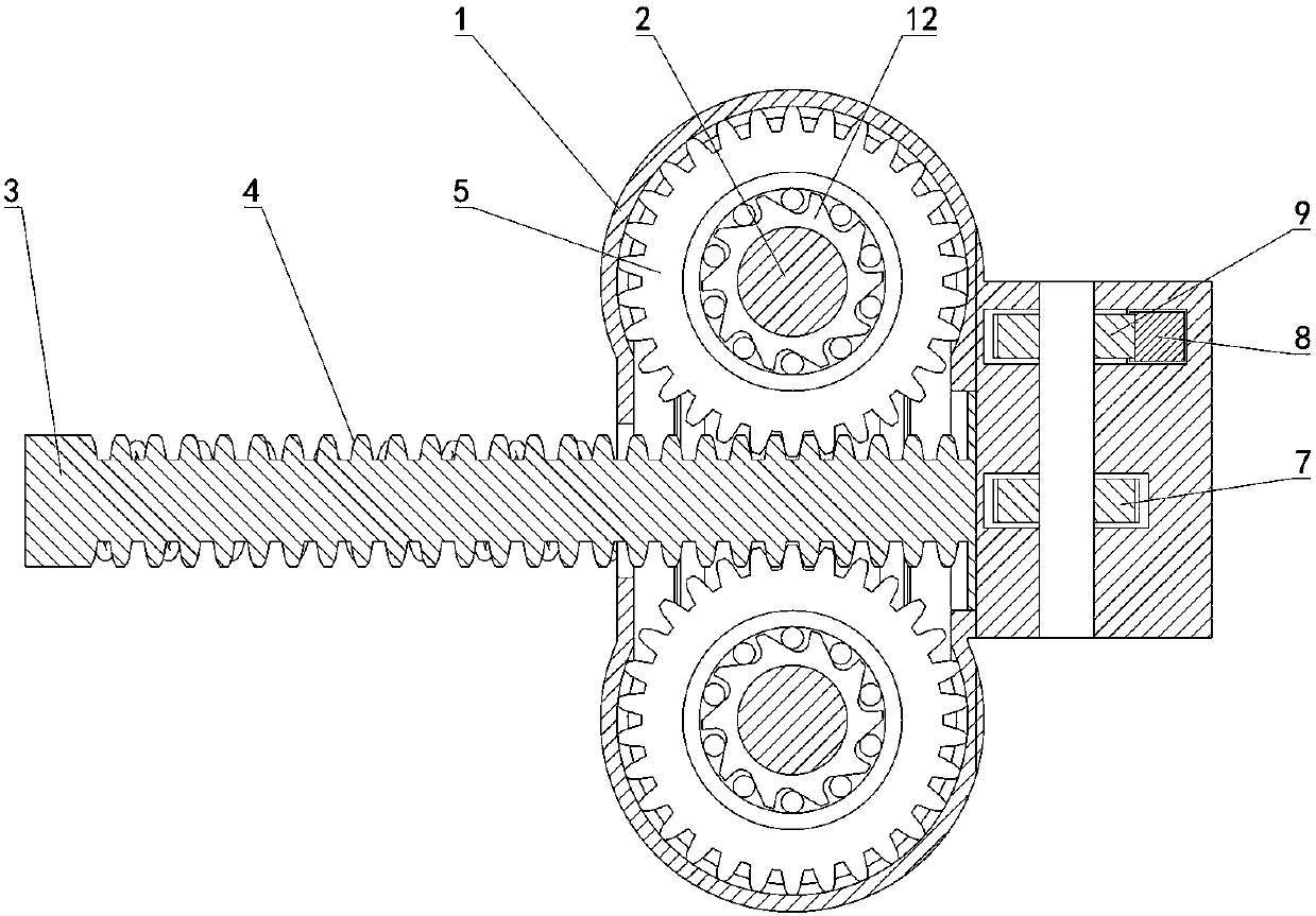
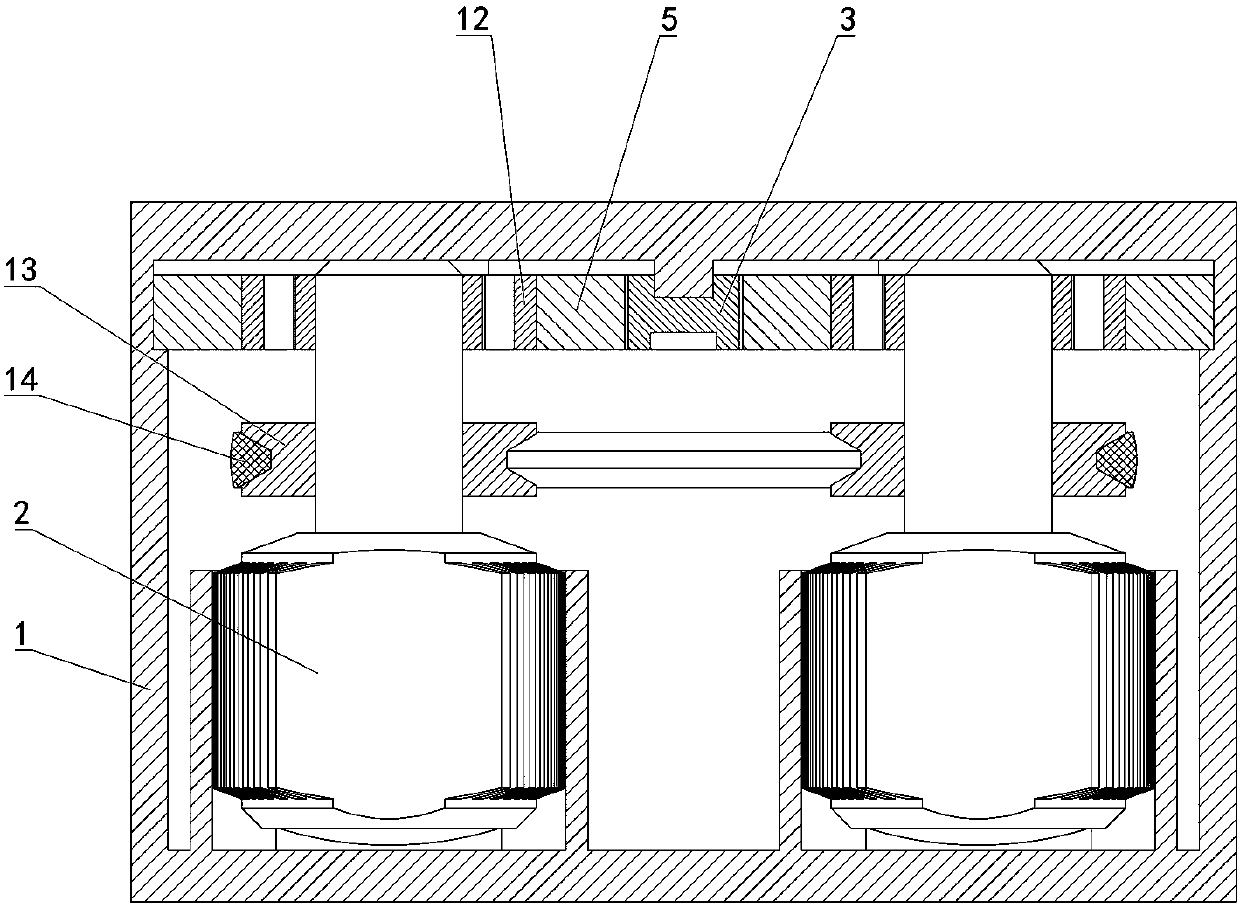
[0015] Depend on Figure 1 to Figure 6 Given, the present invention comprises frame 1 and two generators 2, is characterized in that, slide block 3 that can slide left and right is housed on frame 1, two generators 2 are respectively placed on the front and rear sides of slide block 3, slide block 3 There are two first racks 4 respectively placed on the front and rear sides of the slider 3. The length direction of the first rack 4 is consistent with the sliding direction of the slider 3. The input shaft of the generator 2 is equipped with a 4. The first gear 5 meshed with each other constitutes a structure in which the input shaft of the generator 2 rotates through the meshing action of the first rack 4 and the first gear 5 when the slider 3 slides left and right on the frame 1;

[0016] The second rack 6 placed below t...


PUM


Abstract

The invention relates a motion kinetic energy conversion and storage device. The motion kinetic energy conversion and storage device comprises a frame and two power generators, and is characterized inthat a sliding block capable of sliding leftwards and rightwards is arranged on the frame; the two power generators are separately arranged on the front and rear sides of the sliding block; the sliding block is provided with two first racks which are separately located on the front and rear sides of the sliding block; the input shaft of each power generator is provided with a first gear which isengaged with the corresponding first rack; a second rack which is located below the sliding block is arranged on the sliding block; a second gear which is engaged with the second rack is arranged on the frame; a third rack which slides vertically and a third gear which is engaged with the third rack are arranged on the frame; and the third gear is coaxially connected with the second gear. The motion kinetic energy conversion and storage device is ingenious in structure; the kinetic energy of inertial motion is fully utilized; and the phase stability of the output currents of the power generators is ensured.

Description

technical field [0001] The invention relates to the technical field of automobile inertial energy utilization, in particular to a device for converting and storing kinetic energy. Background technique [0002] The speed-up and deceleration of the car are mainly completed by the engine and the brake system. During the speed-up or deceleration process, the inertial force of the vehicle speed up or down is relatively large, but the current vehicle design does not make effective use of the inertial force, resulting in waste of energy. [0003] At the same time, during the driving process of the car, the unevenness of the road surface will cause the vehicle to bump, shake, etc. The generated kinetic energy is usually ignored by people and has not been utilized reasonably and effectively. Contents of the invention [0004] In view of the above situation, in order to make up for the technical deficiencies existing in the prior art, the present invention provides a kinetic energ...

Claims


Application Information

Patent Timeline
Patent Type & Authority Applications(China)
IPC IPC(8): F03G3/00F03G7/08
CPCF03G3/00F03G7/08
Inventor 张伟郜福超
Owner 泉州市艺家好家居装饰有限公司
Learn More