
Distributed radio frequency electronic system and signal processing method

An electronic system and signal processing device technology, applied in the field of signal processing, can solve the problems of multiple noises, phase changes that cannot be ignored, and high cost, and achieve high phase stability and ensure the effect of operation synchronization

Active Publication Date: 2019-11-05
BEIJING CHANGFENG BROADCASTING COMM EQUIP
View PDF4 Cites 0 Cited by
  • Summary
  • Abstract
  • Description
  • Claims
  • Application Information

AI Technical Summary

Problems solved by technology

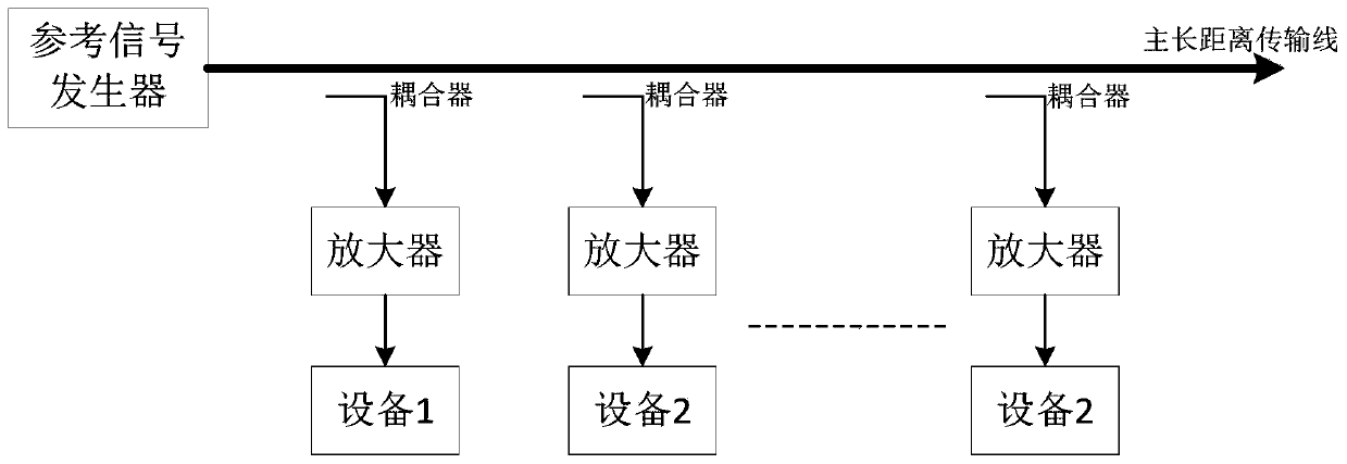
[0004] The disadvantages of the existing technical solutions are: using the combined transmission method of cables and optical cables may introduce more noise and strays in the process of electric-to-optical conversion; simply using a phase-stable cable cannot solve the long-term drift and noise jitter of the reference signal Secondly, the phase change caused by the system with high transmission signal frequency cannot be ignored, and the high phase stability of the reference signal cannot be achieved simply by using a stable phase cable; For experimental sites or outdoor environments, it is impossible to ensure good ambient temperature stability, or to achieve the required ambient temperature stability, the price paid is too high; in addition, some radio frequency electronic systems require that the phase of the signal received by the equipment The stability is within ±1°. The possible reference signal frequency of these systems with such high requirements for phase stability is 100MHz, or a higher system operating frequency, then the corresponding short-term signal stability may be hundreds of femtoseconds The magnitude within (1fs=1e-15s), the long-term stability of the signal may be within the magnitude of 1 picosecond (1ps=1e-12s), or even higher, but none of the above existing technical solutions can achieve such a high index The phase stability effect of

Method used


Image

  • Distributed radio frequency electronic system and signal processing method
  • Distributed radio frequency electronic system and signal processing method
  • Distributed radio frequency electronic system and signal processing method

Examples


Embodiment 1

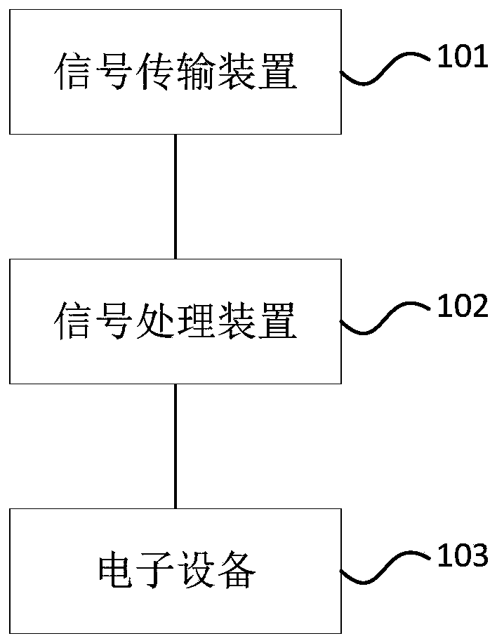
[0048] figure 2 It is a schematic diagram of a distributed radio frequency electronic system provided by Embodiment 1 of the present invention. The system specifically includes: at least one electronic device 103, a signal transmission device 101, and a signal processing device 102 connected to the electronic device 103 in one-to-one correspondence;

[0049] The signal transmission device 101 is electrically connected to each signal processing device 102, and is used to transmit the generated reference signal to each electronic device 103 through each signal processing device 102;

[0050] Each signal processing device 102 is configured to perform phase processing on the received reference signal, and send the processed stable reference signal to the corresponding connected electronic equipment 103, so that each electronic equipment 103 operates synchronously under the same clock reference.

[0051] Wherein, the reference signal refers to a signal that provides the same time ...

Embodiment 2

[0058] Figure 3a and Figure 3b It is a schematic diagram of the distributed radio frequency electronic system provided by the second embodiment of the present invention, and this embodiment is specific to the first embodiment. In this embodiment, the signal transmission device 101 is embodied as:

[0059] The signal transmission device 101 includes: a signal generator 201, a phase-locked loop 202, and a signal transmission main feeder 203;

[0060] The signal generator 201 is electrically connected to the signal input end of the phase-locked loop 202, and is used to generate an initial reference signal and output it to the phase-locked loop 202;

[0061] The phase-locked loop 202 is connected to each signal processing device through the signal transmission main feeder 203, and is used for performing fixed-frequency processing on the input initial reference signal, and outputs the reference reference signal and transmits it to each signal processing device through the signa...

Embodiment 3

[0083] Figure 4a and Figure 4b It is a schematic diagram of the distributed radio frequency electronic system provided by the third embodiment of the present invention, and this embodiment is specific to the first embodiment. In this embodiment, the signal transmission device 101 is embodied as:

[0084] The signal transmission device 101 includes: a signal generator 301, a phase-locked loop 302, and a signal transmission main feeder 303;

[0085] The signal generator 301 is electrically connected to the signal input end of the phase-locked loop 302, and is used to generate an initial reference signal and output it to the phase-locked loop 302;

[0086] The phase-locked loop 302 is connected to each signal processing device through the signal transmission main feeder 303, and is used to perform fixed-frequency processing on the input initial reference signal, output the reference reference signal and transmit it to each signal processing device through the signal transmiss...


PUM


Abstract

The embodiment of the invention discloses a distributed radio frequency electronic system and a signal processing method. The system comprises at least one electronic equipment, a signal transmissiondevice and signal processing devices connected with the electronic equipments in a one-to-one correspondence mode. The signal transmission device is electrically connected with each signal processingdevice and is used for transmitting the generated reference signal to each electronic equipment through each signal processing device; and the at least one signal processing device is used for carrying out phase processing on the received reference signal and sending the processed stable reference signal to the correspondingly connected electronic equipment, so that the electronic equipment worksunder the same clock benchmark and synchronously operates under the same clock benchmark. According to the embodiment of the invention, the problem of reference signal phase change caused by all factors causing cable electrical length change can be avoided, and high-phase stability transmission of the reference signal in the coaxial cable can be realized, so that operation synchronization among equipment in a distributed radio frequency electronic system is ensured.

Description

technical field [0001] Embodiments of the present invention relate to the technical field of signal processing, and in particular to a distributed radio frequency electronic system and a signal processing method. Background technique [0002] In engineering applications, we often need radio frequency electronic systems in a distributed layout. These radio frequency electronic systems contain the equipment required in engineering applications, and each equipment distributed in different locations makes the distribution distance of the entire system possibly exceed the range of hundreds to thousands of meters. In actual work, these devices in the radio frequency electronic system are often required to operate synchronously, and improving the phase stability of the system reference signal makes the signals between each device have good coherence, which is often to ensure that each device in the system An efficient solution that runs synchronously. [0003] At present, distrib...

Claims


Application Information

Patent Timeline
Patent Type & Authority Applications(China)
IPC IPC(8): H04B1/12H04B3/462H04B3/56H04L7/033G02B6/44
CPCG02B6/4401H04B1/12H04B3/462H04B3/56H04B2203/5487H04L7/033
Inventor 李艳东王志宇付浩然刘巍姚少峰姜泽飞高建超赵军罗杰斌李慧君况学伟刘旺史晓雄高锐达
Owner BEIJING CHANGFENG BROADCASTING COMM EQUIP
Learn More