Portable outdoor tennis wall

A portable, outdoor technology, used in rackets, sports accessories, etc., can solve the problems of lack of shielding measures, reduced service life, easy sunburn on elastic walls, etc., and achieves the effect of strong sun protection, easy operation and high cost performance.

Inactive Publication Date: 2018-03-09
孙伟志
View PDF1 Cites 0 Cited by
  • Summary
  • Abstract
  • Description
  • Claims
  • Application Information

AI Technical Summary

Problems solved by technology

[0004] When the elastic wall in this design is used outdoors, it lacks the necessary shielding measures to protect against the sun. In high temperature weather, the elastic wall is easily sunburned, which reduces its service life

Method used


Image

  • Portable outdoor tennis wall
  • Portable outdoor tennis wall

Examples


Embodiment 1

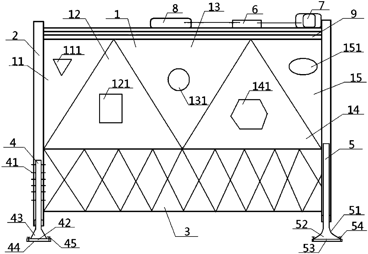
[0036] see figure 1 - figure 2 , a portable outdoor tennis wall, comprising an elastic wall 1, a support fixed column 2 and a storage net 3, the left and right sides of the elastic wall 1 are respectively connected to the inner surface of a support fixed column 2, the bottom of the elastic wall 1 and the The top of the storage net 3 is connected, and the left and right sides of the storage net 3 are respectively connected to the inner surface of a supporting fixed column 2;

[0037] The elastic wall 1 includes five elastic areas, namely No. 1 elastic area 11, No. 2 elastic area 12, No. 3 elastic area 13, No. 4 elastic area 14, and No. 5 elastic area 15. The No. 1 elastic area 11 The left side of the left side is connected with the inner side of the support fixed column 2 on the left side, the right side of the No. 1 elastic zone 11 is connected with the No. 3 elastic zone 13 after passing through the No. 2 elastic zone 12, and the No. 3 elastic zone 13 passes through the No....

Embodiment 2

[0040] Basic content is the same as embodiment 1, the difference is:

[0041] A No. 1 quasi-target 111 is arranged in the middle of the No. 1 elastic zone 11, a No. 2 quasi-target 121 is set in the middle of the No. 2 elastic zone 12, and a No. 3 quasi-target is set in the middle of the No. 3 elastic zone 13. 131, No. 4 quasi-target 141 is arranged in the middle of the No. 4 elastic zone 14, No. 5 quasi-target 151 is set in the middle of the No. 5 elastic zone 15, and No. 1 quasi-target 111, No. 2 quasi-target Target 121, No. 3 quasi-target 131, No. 4 quasi-target 141 and No. 5 quasi-target 151 are all made of buffer materials. The shape of No. 1 quasi-target 111 is a triangle, the shape of No. 2 quasi-target 121 is a rectangle, the shape of No. 3 quasi-target 131 is circular, and the shape of No. 4 quasi-target 141 is hexagonal. The shape of No. quasi-center target 151 is ellipse.

Embodiment 3

[0043] Basic content is the same as embodiment 1, the difference is:

[0044] The bottom of the supporting fixed column 2 on the left side is a hollow structure, and its inner wall is slidingly matched with the outer wall of the left movable leg 4. The outer wall of the left movable leg 4 is provided with a plurality of fixed pins 41, and the inner walls of the fixed pins 41 End is connected with the outer wall of left movable leg 4, and the outer end of fixed pin 41 extends to the outside of support fixed column 2 after passing through the pin hole that offers on the support fixed column 2, and the bottom of left movable pile leg 4 and left pile Boot 42 is connected. Described left spud shoe 42 comprises left abutment 43 and the left fixed platform 44 that is connected with its bottom, and the two ends of this left fixed platform 44 are connected with ground by left fixed pin 45, and the cross section of left abutment 43 is upper. A trapezoidal shape with a narrow bottom and...


PUM


Abstract

A portable outdoor tennis wall, comprising an elastic wall, a support fixed column and a storage net, the bottom of the elastic wall is connected to the top of the storage net, and the left and right sides of the elastic wall and the storage net are clamped between the two support fixed columns Between the inner sides, the top of the elastic wall is provided with a rolling curtain device, the driving shaft of the rolling curtain device is connected to the output end of the driving motor, and the driving motor is electrically connected to the power supply through the temperature controller, and the elastic wall is divided into five parts. Each area has the effect of exercising hitting accuracy and fixing tennis technical movements. This design not only has strong sun protection and rich training means, but also has rich lifting means and wide application range.

Description

technical field [0001] The invention relates to a tennis training facility, in particular to a portable outdoor tennis wall, which is particularly suitable for providing a portable outdoor tennis wall that can automatically block and has strong sun protection. Background technique [0002] Tennis, together with golf, bowling, and billiards, is known as the world's four major gentleman's sports. Its unique charm has long been deeply rooted in the hearts of the people. It is a sport suitable for all ages, and it is more and more loved by our people. But at present, due to the limitation of the venue, the development of tennis is hindered, especially in colleges and universities or various sports centers, the limitation of the venue has become the biggest obstacle restricting the development of tennis. For this reason, tennis walls have appeared to alleviate the limitation of the venue. The tennis wall generally includes the wall and the supporting columns connected on both sid...

Claims


Application Information

Patent Timeline
IPC IPC(8): A63B69/38
CPCA63B69/38A63B69/0097A63B2102/02A63B2220/72A63B2220/833A63B2225/093A63B2225/30
Inventor 孙伟志
Owner 孙伟志
Why Eureka
Try Eureka