
Dynamic model control method of chamfering position of intermediate roll in 20-high rolling mill

A control method and a dynamic model technology, applied in the field of steel rolling, can solve problems such as unsatisfactory stability requirements and very high experience requirements, and achieve the effect of eliminating the phenomenon of rolling broken strips, reducing the phenomenon of broken strips, and preventing uncertainty

Active Publication Date: 2020-06-23
BAOSHAN IRON & STEEL CO LTD
View PDF6 Cites 0 Cited by
  • Summary
  • Abstract
  • Description
  • Claims
  • Application Information

AI Technical Summary

Problems solved by technology

[0005] Due to the change of the width of the rolled strip and the switching of steel types, the position of a middle chamfer needs to be adjusted. At present, manual adjustment is generally used for control, but there are very large errors, and the experience of personnel is very demanding. High, unable to meet stability requirements

Method used


Image

  • Dynamic model control method of chamfering position of intermediate roll in 20-high rolling mill
  • Dynamic model control method of chamfering position of intermediate roll in 20-high rolling mill
  • Dynamic model control method of chamfering position of intermediate roll in 20-high rolling mill

Examples


Embodiment

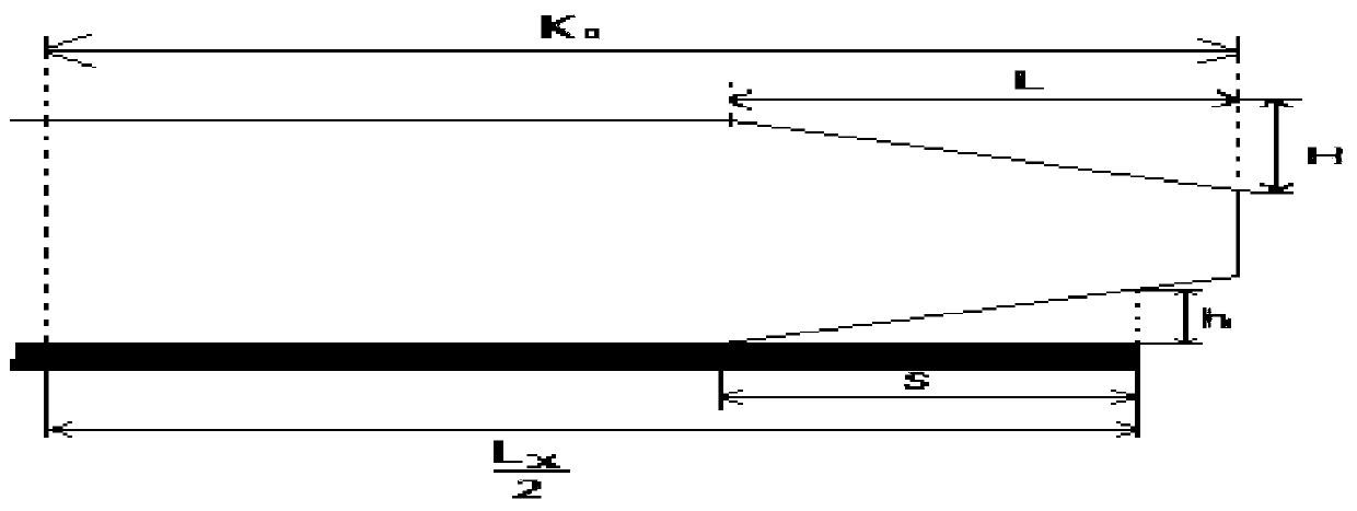
[0148] The present invention has been used in a single-stand 20-high rolling mill in a steel mill to roll high-grade silicon steel products. The single-stand rolling mill has a total stroke To of the middle shifting oil cylinder of 170mm, and the distance between the center of the rolling mill and the edge of the middle distance K 0 It is 835mm.

specific Embodiment

[0150] 1. Use an intermediate roll with a chamfering length of 300mm and a depth of 0.44mm, a rolling width of 1200mm, and a product with a deformation resistance of 510Mpa. The stiffness influence coefficient is 1.02, and the roll stiffness influence coefficient is 1.03; The initial setting position of the roller cylinder is 48.69, which can ensure that the value of the edge plate type I is obtained as follows Figure 5 stable plate type.

[0151]

[0152] 2. Use an intermediate roll with a chamfer length of 375mm and a depth of 0.67mm, a rolling width of 1000mm, and a product with a deformation resistance of 400Mpa. The stiffness influence coefficient is 1.02, and the roll stiffness influence coefficient is 1.03; The initial setting position of the roller oil cylinder is 115.92, which can ensure that the value of the edge plate type I is obtained as follows Figure 6 stable plate type.

[0153]

[0154] The method for controlling the dynamic model of the chamfering p...


PUM


Abstract

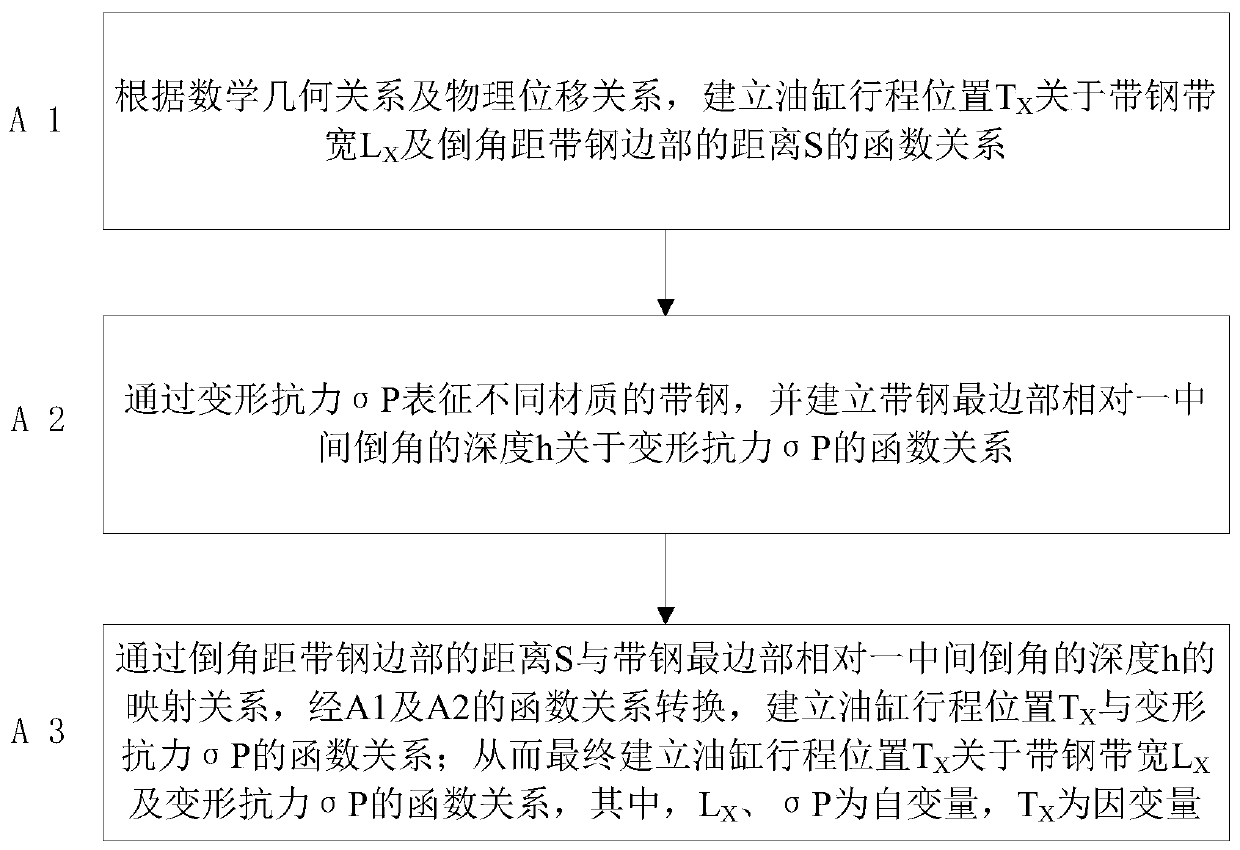
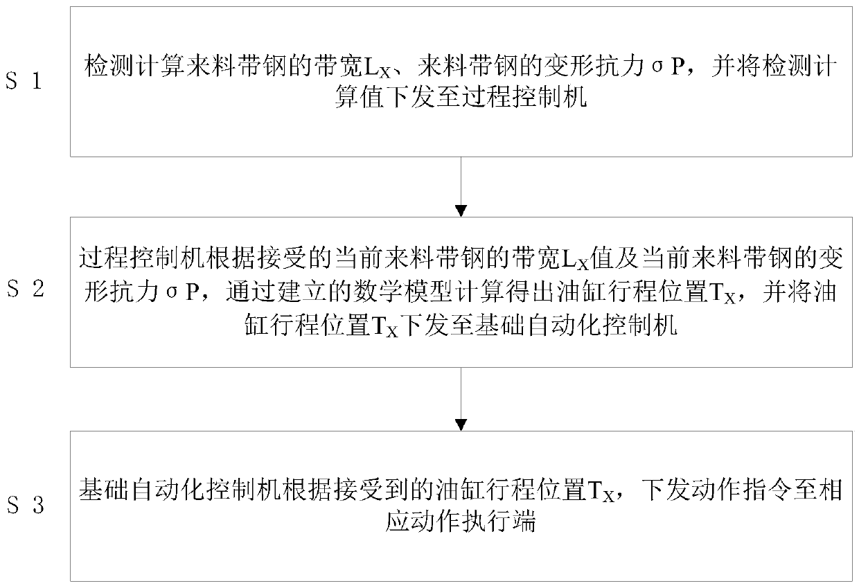
Provided is a control method of a dynamic model of a chamfering position of a middle roller of a 20 rolling mill. The chamfering position is represented through the stroke position of an oil cylinder,and strip steel of different strip widths and different materials can be responded to; on the basis, dynamic modification control is further introduced, and the dynamic modification of the stroke position of the oil cylinder is realized on the basis of responding to the different strip widths and different materials of the strip steel. By means of the device, by designing the position model of achamfer of the middle roller, the uncertainty caused when the position of the middle moving oil cylinder is manually set is effectively prevented, the dynamic response to the changes of the differentmaterial widths and materials is realized, the rolling strip breakage phenomenon caused by the changes of the material widths and materials is eradicated, and finally the strip breakage phenomenon caused by the inaccuracy of the initial setting of the stroke position of the middle chamfering oil cylinder is reduced by introducing the model for self-learning modification.

Description

technical field [0001] The invention belongs to the technical field of steel rolling, and in particular relates to a dynamic model control method for the chamfering position of an intermediate roll of a 20-roll rolling mill. Background technique [0002] At present, the rolling of oriented silicon steel, high-grade non-oriented silicon steel, stainless steel, special steel, high-strength steel and ultra-thin strips in the world is mainly carried out by 20-roll single-stand rolling mills, that is, using one stand and multiple rolls for round-trip rolling. Reciprocating rolling. [0003] The main means of controlling the profile of a single-stand rolling mill is the movement of an intermediate roll, which is controlled by the chamfering on both sides of an intermediate roll. The relative position of the edge, and then control the thickness and shape of the edge strip. The movement of an intermediate roll is performed through the oil cylinder connected to the transmission sid...

Claims


Application Information

Patent Timeline
Patent Type & Authority Patents(China)
IPC IPC(8): B21B37/40
CPCB21B37/40
Inventor 朱华群赵彬宿德军唐伟宋艳丽
Owner BAOSHAN IRON & STEEL CO LTD
Learn More