
Deep sea full-section observing turbulent mixing section plotter

A profile observation and profiler technology, which is applied in the direction of instruments, measuring devices, components of the damping parts of the measuring device, etc., can solve the problems of probe data acquisition interference, instrument self-vibration, measurement signal interference, etc., to improve its own stability , improve stability and reduce interference

Inactive Publication Date: 2018-03-09
INST OF DEEP SEA SCI & ENG CHINESE ACADEMY OF SCI
View PDF12 Cites 22 Cited by
  • Summary
  • Abstract
  • Description
  • Claims
  • Application Information

AI Technical Summary

Problems solved by technology

However, the two above-mentioned mixed ocean turbulence measuring instruments have the following defects: 1. The measuring instrument is designed with an integrated structure, and the instrument has its own vibration during ocean observation, which interferes with the data collection of the probe; the measuring instrument is in the process of underwater movement. Vibration signals will be generated due to the influence of lateral ocean currents and its own wake, which will seriously interfere with the real measurement signals of fast temperature and shear probes
2. Since the measuring instruments cannot carry out autonomous control of underwater motion attitude, etc., there are two blind spots in the instrument observation, that is, the direct observation of the upper sea-air interface near the water body boundary layer and the seabed water-solid interface near the water body boundary layer cannot be realized. Constrains the progress of research on the two interfacial substances and energy exchange mechanisms

Method used


Image

  • Deep sea full-section observing turbulent mixing section plotter
  • Deep sea full-section observing turbulent mixing section plotter
  • Deep sea full-section observing turbulent mixing section plotter

Examples


Embodiment Construction

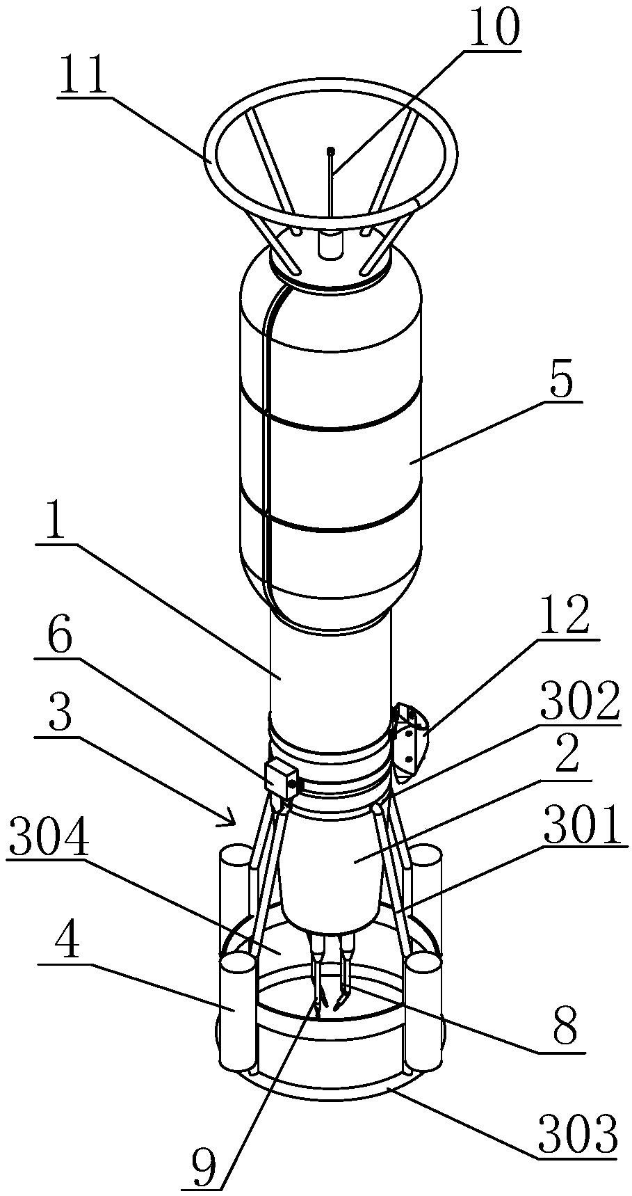
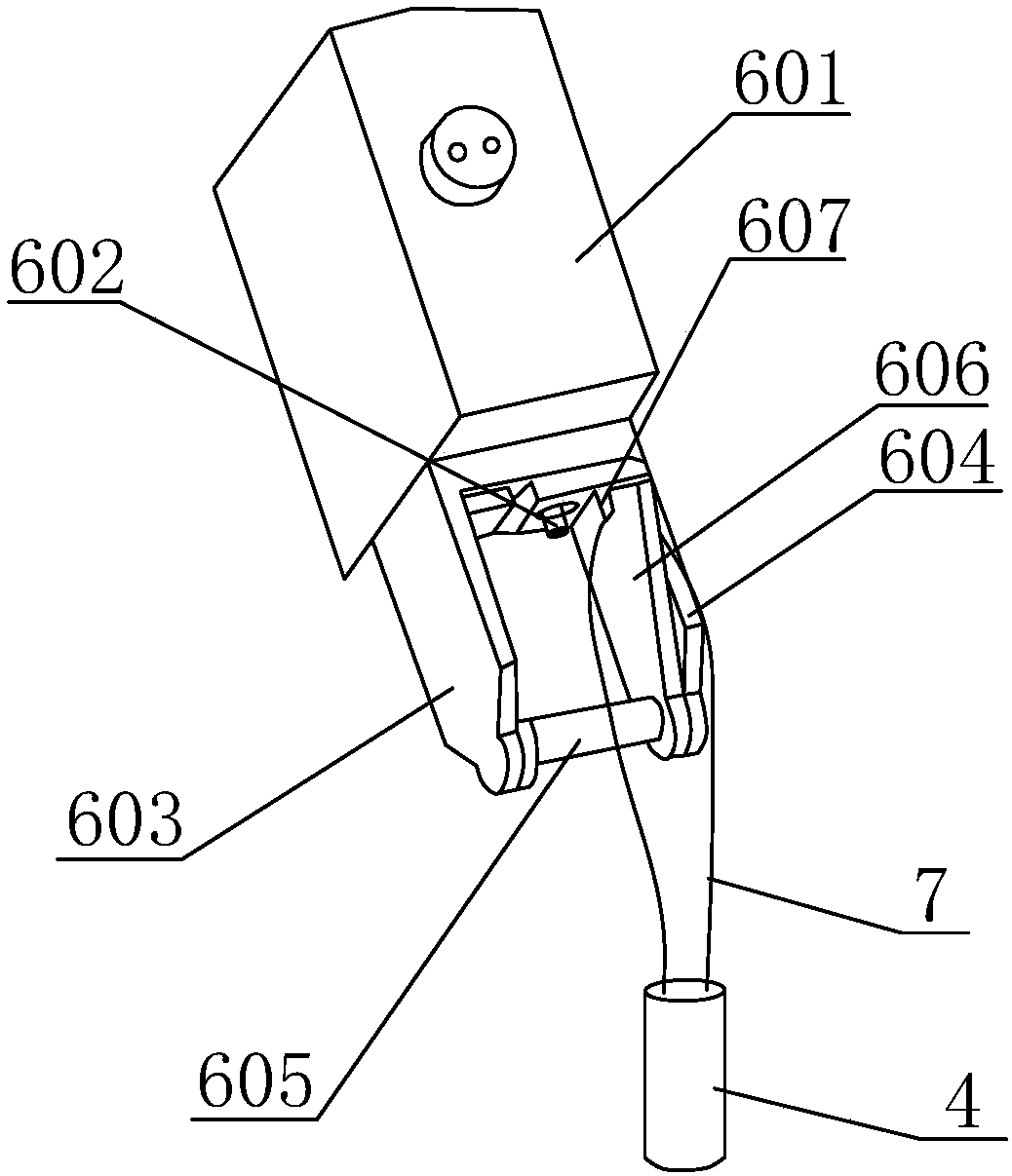
[0022] In conjunction with the accompanying drawings, a deep-sea full-section observation turbulence mixing profiler includes an instrument cabin 1 and a probe cabin 2. The instrument cabin 1 and the probe cabin 2 adopt a split design, and a flexible damper is connected between the instrument cabin 1 and the probe cabin 2. Shock coupling frame 3. The flexible shock-absorbing coupling frame 3 includes a plurality of support rods 301, one end of all the support rods 301 is connected to the fixed ring 302, the fixed ring 302 is connected to the instrument cabin 1, and the other ends of all the support rods 301 are connected to the probe protection On the ring 303, all the support rods 301 surround a protected space 304, the probe cabin 2 is built in the protected space 304, the outer wall of the probe cabin 2 is fixed to part of the support rods 301, and the electrical components between the probe cabin 2 and the instrument cabin 1 Connection via watertight cable.

[0023] A plu...


PUM


Abstract

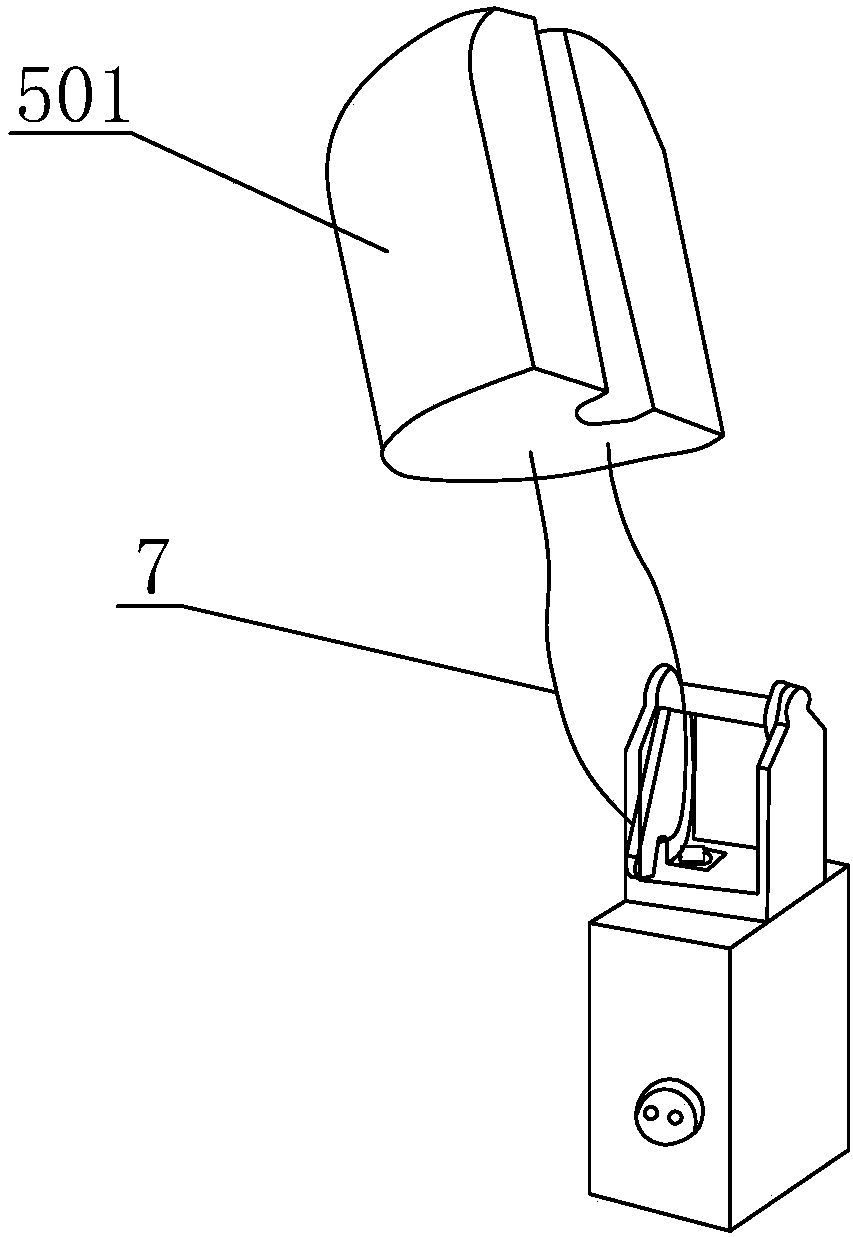
The invention discloses a deep sea full-section observing turbulent mixing section plotter which comprises an instrument bin and a probe bin. The instrument bin and the probe bin adopt the split design, a flexible damping coupling frame is connected between the instrument bin and the probe bin, the flexible damping coupling frame comprises a plurality of supporting rods, one ends of all supportingrods are connected to a fixing ring, the fixing ring and the instrument bin are connected, the other ends of all the supporting rods are connected to a probe protecting ring, all the supporting rodsform a protecting space, the probe bin is arranged inside the protecting space, and electric devices between the probe bin and the instrument bin are connected through a watertight cable; a pluralityof weights are arranged on the flexible damping coupling frame, a floating body material block is arranged outside the instrument bin, and all the weights and the floating body material block are allcontrolled by a load rejection mechanism to be released. By freely adjusting the observation position of the probe bin, direct observation of the full section from the sea interface to the seabed boundary layer is achieved; meanwhile, the two bins are flexibly connected, and the interference caused by self-vibration can be lowered.

Description

technical field [0001] The invention relates to the technical field of ocean mixing on-site observation, in particular to a deep-sea full-section observation turbulence mixing profiler. Background technique [0002] At present, the ocean turbulence mixing measurement instruments are mainly divided into the following two categories: ship-mounted cable turbulence profiler and ship-mounted cable-free turbulence profiler. The former measures the water depth range from 500 meters to 2000 meters; the latter has no cable, and the instrument basically falls at a constant speed of "free fall". When the instrument reaches the specified depth, it completes the mixed profile measurement by throwing the load and floating up. This type of instrument is suitable for deep sea For the measurement of turbulent mixing, the measurement range of the current commercialized instrument is 2000 meters to 4000 meters. However, the two above-mentioned mixed ocean turbulence measuring instruments have...

Claims


Application Information

Patent Timeline
IPC IPC(8): G01D3/036G01D3/08G01D11/10G01D21/02
CPCG01D3/036G01D3/0365G01D3/08G01D11/10G01D21/02
Inventor 田川
Owner INST OF DEEP SEA SCI & ENG CHINESE ACADEMY OF SCI
Learn More