

Peak Tracking Method of UAV Altitude Signal
A technology of height signal and height tracking, applied in the field of radar, can solve the problem of low real-time tracking of UAV height signal, and achieve the effect of avoiding abnormal height value, reducing operation time and improving refresh rate.
- Summary
- Abstract
- Description
- Claims
- Application Information
AI Technical Summary
Problems solved by technology
Method used
Image


Examples
Embodiment 1
[0011] Embodiment 1: a method for processing radar signals of a radar altimeter system of a plant-protected rotor UAV, comprising the following steps:
[0012] S1. AD data collection;
[0013] The AD data collection is digitized through AD sampling, the number of data points N collected by AD, after removing part of the data, the number of remaining points is N_s.
[0014] S2. To direct current, this step is an optional step;
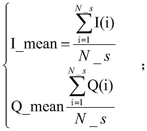
[0015] (1) Calculate the mean value I_mean and Q_mean of the respective N_s data of the I road and the Q road respectively;
[0016]
[0017] (2) wherein I is the time-domain data of the I road, Q is the time-domain data of the Q road, I_mean is the mean value of the I road, and Q_mean is the mean value of the Q road;
[0018] (3) each data of the I road and the Q road is subtracted from the mean value of each road;
[0019] (4) The calculation formula of IQ data to DC is: Wherein, I' is the data after removing the direct current, and Q' is ...
Embodiment 2
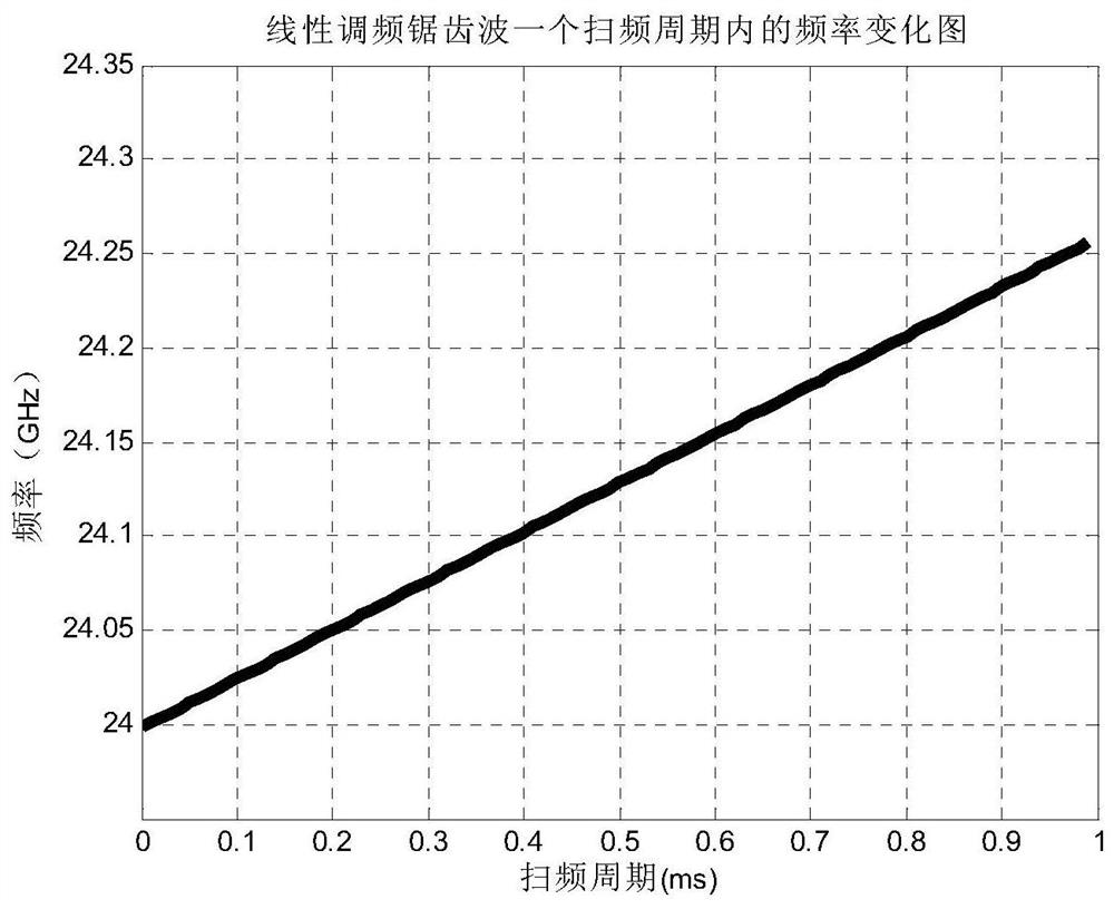
[0050] Embodiment 2: The patent application with the application publication number CN104678397A discloses an ultrasonic altimeter for small unmanned aerial vehicles, which uses an ultrasonic method to measure the height from the ground when the unmanned aerial vehicle is close to the ground, so as to realize the autonomy of the unmanned aerial vehicle Takeoff and landing function, but the ultrasonic altimeter described in the patent has a maximum range of 11m, which is far from enough for plant protection drones to spray pesticides. Therefore, in order to improve the ranging range of the UAV altimeter between 30 and 40m and ensure the ranging accuracy of about 0.2m, a UAV altimeter based on millimeter-wave radar was invented. Moreover, compared with other detection methods, millimeter-wave radar also has the advantages of stable detection performance, good environmental adaptation, small size, low price, and can be used in relatively severe rainy and snowy weather.
[0051] A...
Embodiment 3
[0105] Embodiment 3: From the technical solutions in the above two embodiments, it can be found that in the technical solutions disclosed in these two embodiments, a peak tracking method of the height signal of the drone is also included. The tracking method is sorted out. Obviously, the tracking method in this embodiment can be supported by the above two embodiments. However, it is a peak tracking method that can be independently applied to the height signal of the drone. , not limited to the technical solutions in the above two embodiments, the tracking method has: the step of tracking the peak point crossing the threshold; and the step of tracking the distance.
[0106] Wherein: the described method of crossing the threshold peak point tracking is:
[0107] Set a peak point threshold factor α, which is used to limit the absolute value of the difference between the detected maximum peak point crossing the threshold and the maximum peak point that appeared in the previous cyc...
PUM
 Abstract
Description
Claims
Application Information