Valve sealing device

A valve sealing and valve body technology, which is applied in the direction of valve device, valve operation/release device, valve lift, etc., can solve problems such as valve damage, reduced use efficiency, and valve cannot be sealed, so as to prolong the service life and solve the problem of using short-lived effect

Inactive Publication Date: 2018-03-13
浙江杭振锅炉有限公司
View PDF0 Cites 2 Cited by
  • Summary
  • Abstract
  • Description
  • Claims
  • Application Information

AI Technical Summary

Problems solved by technology

[0003] The purpose of the present invention is to provide a valve sealing device, which has the advantages of being able to seal the inside of the valve to prevent damag

Method used


Image

  • Valve sealing device
  • Valve sealing device

Examples


Embodiment Construction

[0015] The following will clearly and completely describe the technical solutions in the embodiments of the present invention with reference to the accompanying drawings in the embodiments of the present invention. Obviously, the described embodiments are only some, not all, embodiments of the present invention. Based on the embodiments of the present invention, all other embodiments obtained by persons of ordinary skill in the art without making creative efforts belong to the protection scope of the present invention.

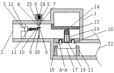
[0016] see Figure 1-2 , a valve sealing device, comprising a valve body 1, a fixed rod 26 is fixedly connected to the bottom of the inner cavity of the valve body 1, and the end of the fixed rod 26 away from the inner wall of the valve body 1 is flexibly connected to the axis of the second bevel gear 9, The left side of the valve body 1 is provided with a water inlet 2, and the top and bottom of the left side of the inner cavity of the valve body 1 are fixedl...


PUM


Abstract

The invention discloses a valve sealing device, which comprises a valve body. A water inlet is opened on the left side of the valve body. The top and the right side of the first fixed block are fixedly connected with a fixed shaft, and the left side of the top of the valve body is fixedly connected with a motor box. The present invention achieves the effect of fixing the second fixed block through the setting of the first support plate, and achieves the fixing of the block through the setting of the groove, and the setting of the sealing pad prevents the leakage of the water flow. The setting achieves the effect that the water flow enters the valve body, and the floating block is moved downward by the pressure of the water flow to drive the fixed sleeve to move. Through the setting of the spring, the floating block is reset by the tension of the spring after the water in the valve body flows out. , At the same time, it solves the problem that the inside of the valve cannot be sealed, resulting in damage to the valve and reducing the use efficiency.

Description

technical field [0001] The invention relates to the technical field of valves, in particular to a valve sealing device. Background technique [0002] The structure of the currently used valve is: including a valve stem, and a valve body provided with a water inlet and a water outlet, an installation port is provided on the top of the valve body, a valve cover is provided on the sealing cover on the installation port, and a valve cover is provided in the valve cover. There is a central hole used to communicate with the interior of the valve body and allow the valve stem to pass through. The valve stem extends into the interior of the valve body from the central hole and is fixed with a valve core. Driven by the driving mechanism, the valve core drives the valve core to block or communicate with the water inlet. and the water outlet, a valve sealing device is provided between the valve stem and the valve cover to seal the gap between the two. The annular groove is filled with...

Claims


Application Information

Patent Timeline
IPC IPC(8): F16K1/04F16K31/04F16K31/20F16K31/53F16K1/36
CPCF16K1/04F16K1/36F16K31/04F16K31/047F16K31/20F16K31/53
Inventor 王立新陈金富
Owner 浙江杭振锅炉有限公司
Why Eureka
Try Eureka