Light emitting device

An optical device and optical component technology, which can be applied to lighting devices, portable lighting devices, light sources, etc., can solve the problems of only illuminating part of the front area, unable to achieve multi-angle and wide-angle lighting, and inconvenient to place and carry.

Inactive Publication Date: 2018-03-13
惠州市洛玛科技有限公司
View PDF7 Cites 2 Cited by
  • Summary
  • Abstract
  • Description
  • Claims
  • Application Information

AI Technical Summary

Problems solved by technology

[0003] With the improvement of people's living standards, the situation of going out to travel has also increased, and the lighting when going out has become a more difficult problem, especially in camping in the wild. Although the flashlight can play a certain role in lighting, it can only illuminate the front part. The area has lighting limitations, and it is impossible to achieve multi-angle and wide-angle lighting, and the flashlight needs to be held in the hand all the time, which is not easy to place and carry. In addition, it is an unavoidable problem to go out to charge

Method used


Image

  • Light emitting device
  • Light emitting device

Examples


Embodiment Construction

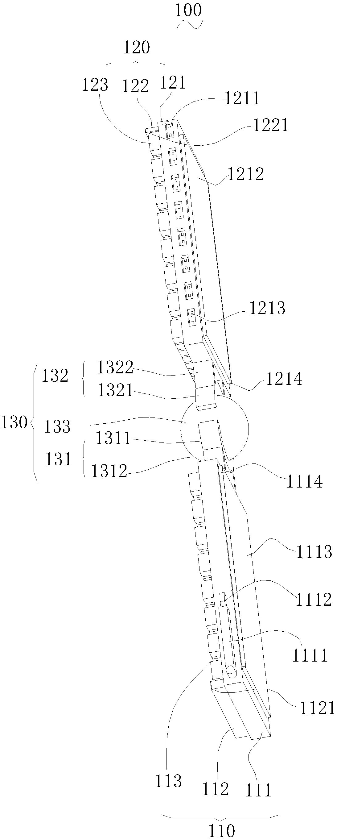
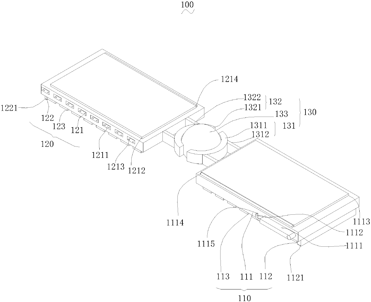
[0018] In order to facilitate the understanding of the present invention, the present invention will be described more fully below with reference to the relevant drawings. The preferred embodiments of the present invention are shown in the drawings. However, the present invention can be implemented in many different forms and is not limited to the embodiments described herein. On the contrary, the purpose of providing these embodiments is to make the disclosure of the present invention more thorough and comprehensive.

[0019] It should be noted that when an element is referred to as being "disposed on" another element, it may be directly on the other element or a central element may also exist. When an element is considered to be "connected" to another element, it can be directly connected to the other element or an intermediate element may be present at the same time. The terms "vertical", "horizontal", "left", "right" and similar expressions used herein are for illustrative ...


PUM


Abstract

The invention relates to a light emitting device. The light emitting device comprises a first light emitting component, a second light emitting component and a rotating component, wherein the rotatingcomponent is positioned between the first light emitting component and the second light emitting component; the first light emitting component comprises a first lamp panel, a first bulging part and aplurality of first LED lamp beads; the second light emitting component comprises a second lamp panel, a second bulging part and a plurality of second LED lamp beads; the rotating component comprisesa first connecting part, a second connecting part and a rotating part; the two ends of the first connecting part are connected with the first lamp panel and the rotating part separately; and the two ends of the second connecting part are connected with the second lamp panel and the rotating part separately. According to the light emitting device, the first lamp panel and the second lamp panel arerotated, the two lamp panels intersect in different planes and are supported on the ground, the illuminating range and angle of the light emitting device are expanded, clamping convex ribs on the second bulging part are clamped in clamping narrow grooves in the first bulging part, so that the light emitting device is convenient for a user to carry around when going out; besides, the solar energy is transformed into electric energy through photovoltaic panels to be stored in the daytime, so as to supply power to the light emitting device during the night.

Description

Technical field [0001] The invention relates to a light emitting device. Background technique [0002] With the progress of the technological revolution, more and more electronic products are quietly entering people’s daily lives. Lighting products have become essential tools for people’s life, work and study. Lighting products in ordinary life are usually fixed in specific locations. Yes, for example, the chandelier is fixed to the ceiling and the table lamp is placed on the table top. [0003] With the improvement of people's living standards, the number of travels has also increased. Lighting when going out has become a more difficult problem, especially when camping in the wild. Although flashlights can play a certain role in lighting, they can only illuminate the front part. Areas have lighting limitations and cannot achieve multi-angle and wide-angle lighting. Moreover, the flashlight needs to be held in the hand all the time when using it, which is not convenient to place a...

Claims


Application Information

Patent Timeline
Patent Type & Authority Applications(China)
IPC IPC(8): F21L4/08F21V14/02F21V17/16F21V23/00F21Y115/10
CPCF21L4/085F21V14/02F21V17/164F21V23/023F21Y2115/10
Inventor 吴玲玲
Owner 惠州市洛玛科技有限公司
Why Eureka
Try Eureka