Electric railway auto-transformer (AT) traction network fault positioning method

A technology for electrified railway and fault location, which is applied to the fault location, fault detection according to the conductor type, and electrical measurement. It can solve the problems of impact, short-circuit data limited, poor positioning accuracy, etc., and achieve the effect of less investment and easy implementation

Active Publication Date: 2018-03-13
SOUTHWEST JIAOTONG UNIV
View PDF7 Cites 17 Cited by
  • Summary
  • Abstract
  • Description
  • Claims
  • Application Information

AI Technical Summary

Problems solved by technology

[0003] 1) The current measurement during short circuit is generally not completely synchronized, and the current transformer may also be saturated, resulting in errors in current measurement;
[0004] 2) The existence of AT leakage reactance makes the slope of AT suction current ratio curve smaller, and the positioning accuracy caused by current error is poor;
[0005] 3) The rail and PW (protection wire) are connected once through CPW (connection wire for protection wire) about 1.5km, which makes the distribution of AT suction current more complicated;
[0006] 4) The short-circuit test will bring impact to the relevant equipment of the power system and traction power supply system, so the number of short-circuit tests is generally relatively small, and the short-circuit data that can be used by the AT suction current ratio method is also very limited
[0007] The fault location accuracy of the AT suction current ratio method is poor

Method used


Image

  • Electric railway auto-transformer (AT) traction network fault positioning method
  • Electric railway auto-transformer (AT) traction network fault positioning method
  • Electric railway auto-transformer (AT) traction network fault positioning method

Examples


Embodiment Construction

[0044] The implementation steps of the present invention will be further described below in conjunction with the drawings and specific embodiments.

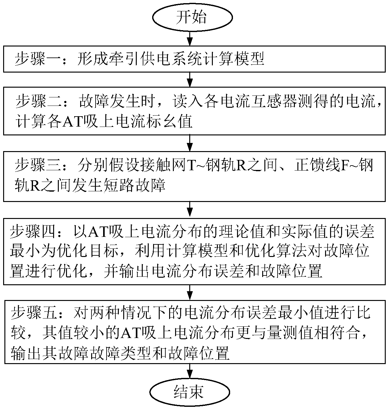
[0045] The implementation steps of this method are as follows: figure 1 shown and explained as follows:

[0046] Step 1. Forming the traction power supply system model:

[0047] The calculation model of AT traction network is established based on multi-conductor transmission line theory or generalized symmetric component method. When the power supply line is long, in order to improve the accuracy of fault location, the influence of power supply line should be considered when modeling.

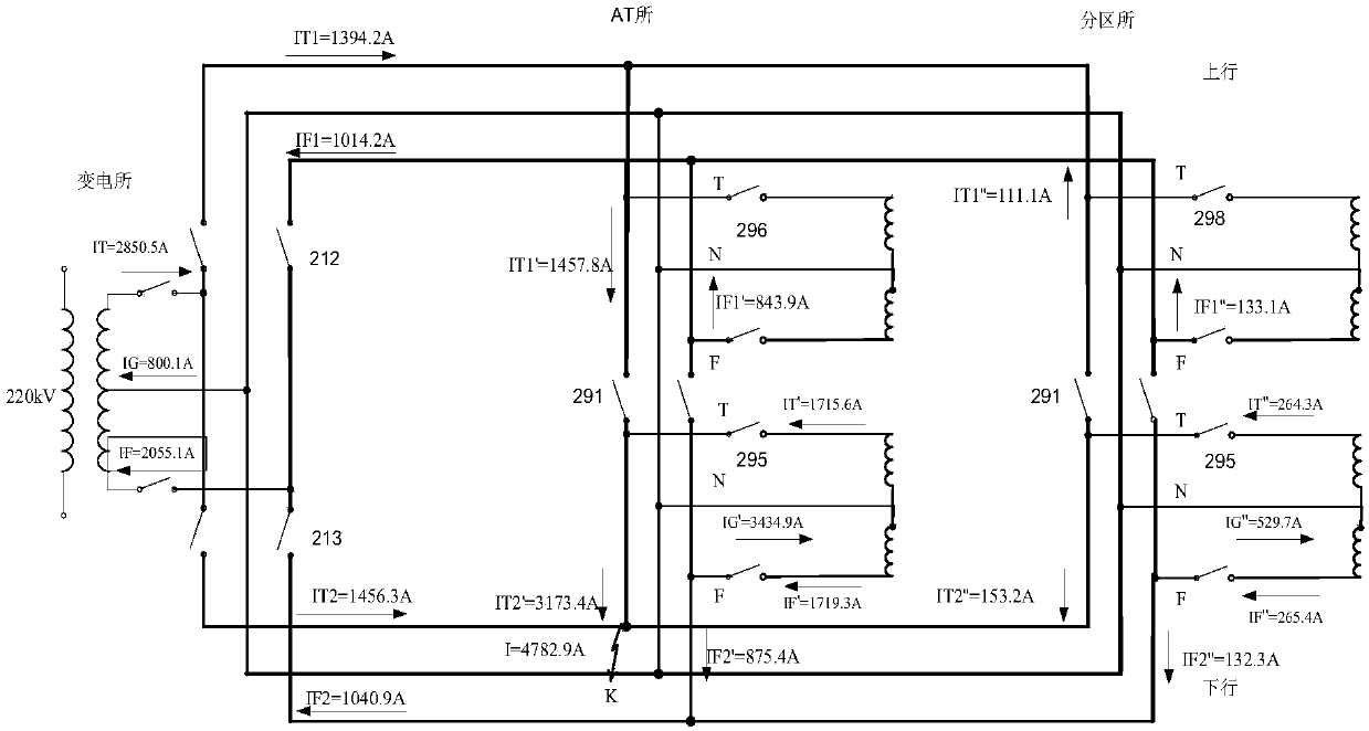
[0048] Step 2. When a fault occurs, read in the current measured by each current transformer, and calculate the per unit value of the current absorbed by each AT:

[0049] When the AT traction network fails, the actual short-circuit current can be obtained by the generalized symmetrical component method according to the measured current of the c...


PUM


Abstract

The present invention discloses an electric railway AT traction network fault positioning method, and relates to the electric railway traction power supply technology field. The electric railway AT traction network fault positioning method can automatically determine the fault types and the fault positions, and the principle of the method comprises the steps of separately hypothesizing that the short circuit faults happen between an overhead line system T and a steel rail R and between a positive feeder line F and the steel rail R, and according to a calculation model of an AT traction network, taking the minimum error of the theoretical value and the actual value of the AT suck current distribution as an optimization target to optimize; comparing the current distribution error minimum values on the two short circuit fault conditions, and defining the fault type corresponding to the smaller numerical value as the fault type of the faults this time and the corresponding positions as the fault positions of the faults this time. Compared with an AT suck current, the method enables the fault positioning errors brought by the AT suck current errors at the two ends of a fault section tobe reduced, is simple in structure and less in investment, is convenient to construct, can be used for the new line construction, and is also suitable for the old line reconstruction.

Description

technical field [0001] The invention relates to the technical field of electric railway traction power supply. Background technique [0002] High-speed railways generally use AT power supply. The structure of the AT traction network is complex and has no backup, so the probability of failure is high. In order to improve the transportation efficiency of the railway, it is necessary to determine the location and type of the fault as soon as possible. There are many existing fault location algorithms. In full parallel operation, the fault location can be located by using the up-down-down current ratio method or the cross-connection current ratio method. For the separate power supply for uplink and downlink of the double-line AT traction network, V stop maintenance or single-line AT traction network, the uplink and downlink current ratio method or the cross-connection line current ratio method is no longer applicable. At this time, the AT suction current ratio method can be u...

Claims


Application Information

Patent Timeline
Patent Type & Authority Applications(China)
IPC IPC(8): G01R31/08
CPCG01R31/086G01R31/088
Inventor 马庆安李群湛刘炜陈民武解绍锋
Owner SOUTHWEST JIAOTONG UNIV
Why Eureka
Try Eureka