Micro switch with forced separation mechanism

A technology of micro switch and separation mechanism, which is applied in the direction of electric switches, electrical components, circuits, etc. It can solve the problems of switch action failure, switch action parameter change, and moving contact piece cannot be reset, so as to prevent material deformation and material thickness increase. thick effect

Active Publication Date: 2018-03-13
ZHANGZHOU JUANMEI ELECTRIC TECH CO LTD
View PDF7 Cites 2 Cited by
  • Summary
  • Abstract
  • Description
  • Claims
  • Application Information

AI Technical Summary

Problems solved by technology

[0006] 2. Most of the micro switches are self-resetting by tension springs, reeds or integral shrapnel. In the initial state, the contacts on the movable contact piece of the switch are usually in contact with the contacts on the normally closed connector. The rocker movement mode is used to realize the forced separation of the switch. When the contact on the movable contact piece contacts the contact on the normally closed connector at the top, one end of the forced separation part moves downward around the fulcrum when the button is pressed down, and the other end of the forced separation part moves The direction is upward, and the forced separation can only be forced to separate when it acts on the moving contact piece downwards. Therefore, the movement direction of the other end of the forced separation is upward and does not work, which also makes it difficult for the micro switch to realize the forced separation function.
[0007] 3. The internal elastic parts of the micro switch mostly use tension springs, reeds or integral shrapnel to trigger the switch to turn on and off. The switching action and reset are all completed by elastic parts. The elasticity of elastic parts is generally relatively small. The forced separation part cannot be reset by itself, and it needs to be reset by the elastic force of the switch shrapnel, but the elastic force of the elastic part of the micro switch is generally too small, and additional force is required to force the separation part to reset, which increases the burden on the elastic part and easily affects the switching characteristics. , when the elastic force of the switch is attenuated, severe cases can lead to the failure of the switch action. If the switch is installed in a vibrating environment, it is easy to cause problems if the vibration of the separating part is forced
[0008] 4. When the micro switch adopts reed or integral shrapnel, because the wall thickness of the moving contact piece is thin and elastic, when the forced separation part acts on the elastic moving contact piece, because the action

Method used


Image

  • Micro switch with forced separation mechanism
  • Micro switch with forced separation mechanism
  • Micro switch with forced separation mechanism

Examples


Embodiment 1

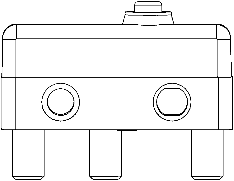
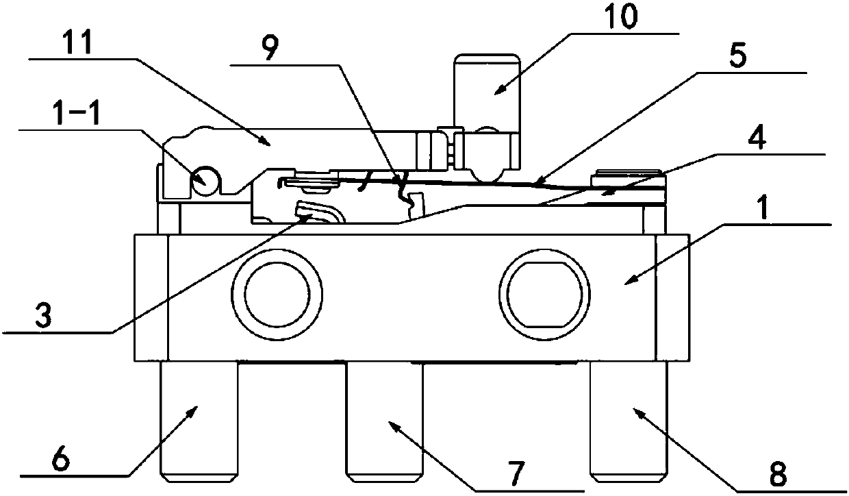
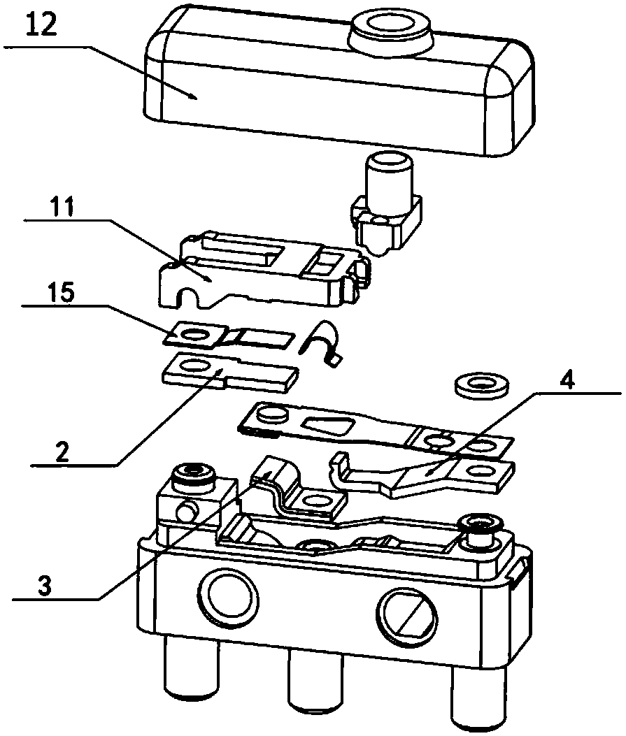
[0044] like figure 1 , figure 2 and image 3 As shown, in the micro switch with a forced separation mechanism of the present invention, the housing 1 is provided with a normally closed static contact assembly and a common terminal static contact assembly, the normally closed static contact assembly is a normally closed static contact 2, and the public The end static contact assembly is a public end static contact 4, and a trigger assembly and an elastic assembly are also provided in the housing. One end of the elastic assembly is electrically connected to the public end static contact assembly, and the other end is electrically connected to the normally closed static contact assembly; The terminal static contact component is provided with a groove, and the above-mentioned elastic component is abutted on the groove. The elastic component can be switched up and down around this groove. A trigger component for driving the movement of the elastic component is connected to the to...

Embodiment 2

[0057] Basically the same as Example 1, the difference is:

[0058] like Figure 8 and Figure 9 As shown, the linkage design of the forced separation part 11 and the button 10 is such that the boss 11-5 of the forced separation part engages with the button groove 10-2, the button 10 moves downward, and the boss 11-5 contacts the groove 10-2 and Drive the forced separation part to rotate.

[0059] The working principle is the same as that of Embodiment 1.

Embodiment 3

[0061] Basically the same as Example 1, the difference is:

[0062] like Figure 10 and Figure 11 As shown, both sides of the forced separation part are provided with bosses 11-5, and both sides of the corresponding button 10 are also provided with grooves 10-2, and the two bosses and grooves are snapped together to realize the button and the forced button during movement. Contact linkage of separating parts.

[0063] The working principle is the same as that of Embodiment 1.


PUM


Abstract

The invention discloses a micro switch with a forced separation mechanism. The micro switch comprises a normally closed static contact piece, a button and an elastic component and further comprises aforced separation piece, wherein one end of the forced separation piece is installed on a shell through a rotary shaft, the other end thereof props against the end surface of the elastic component, and the button and the forced separation piece are linked so as to force the normally closed static contact piece to separate from the elastic component. The micro switch is provided with the forced separation piece, so that when a movable contact and a static contact cannot separate from each other normally, the movable contact and the static contact are forced to separate so as to keep the electric appliance safe. The micro switch has a bright application prospect.

Description

technical field [0001] The invention relates to a micro switch, in particular to a micro switch with a forced separation mechanism. Background technique [0002] The micro switch is a contact mechanism with a small contact interval and a quick-action mechanism, which performs switching actions with a specified stroke and a specified force. It is covered with a casing and has a trigger rod on the outside. Small, hence the name micro switch. The external mechanical force acts on the action reed through the transmission element (press pin, button, lever, roller, etc.). Tap to quickly connect or disconnect. When the force on the transmission element is removed, the action reed produces a reverse action force, and when the reverse stroke of the transmission element reaches the action critical point of the reed, the reverse action is completed instantaneously. The contact spacing of the micro switch is small, the action stroke is short, the pressing force is small, and the on-o...

Claims


Application Information

Patent Timeline
IPC IPC(8): H01H13/62
CPCH01H13/62
Inventor 戴四川
Owner ZHANGZHOU JUANMEI ELECTRIC TECH CO LTD
Why Eureka
Try Eureka