
Method for driving oscillating body and electromagnetic driving mechanism

A driving mechanism and swing body technology, which is applied in electronic commutation motor control, DC motor speed/torque control, electrical components, etc., can solve the problems of automatic swing swing body not being marketed, pinching children, and loud noise , to achieve the effect of avoiding personal injury or mechanical damage, highlighting safety features, and reducing the degree of harm

Inactive Publication Date: 2005-02-16
张国瑞
View PDF6 Cites 12 Cited by
  • Summary
  • Abstract
  • Description
  • Claims
  • Application Information

AI Technical Summary

Problems solved by technology

Using a motor or a coil to drive the magnetic core as a power source needs to convert the force of rotation or linear motion into the force of the shaft, and the conversion process is mainly realized by mechanical devices, so the structure is more complicated, the efficiency is relatively low, and there is a problem when applying force. Vibration, high noise, and of course the manufacturing cost is relatively high; in addition, the swing period of the swing body using this driving method is often fixed, not only the length of the cantilever cannot be adjusted, but also the change of excessive load will also be caused by frictional resistance and The change of air resistance affects the swing period of the swing body
And the driving method proposed by US3883136 and JP53074953 has only one magnetic pole interaction, and the distance between the permanent magnet and the iron core of the electromagnet is difficult to control smaller, so the efficiency is also relatively low; moreover, how to ensure the magnetic relay When the switch is closed, the oscillating body has crossed the middle position, so that the relay switch is closed when the switch has not crossed the middle position, and the reverse thrust is not applied to the oscillating body; it is also a problem that needs to be solved in this method; Alternate changes in the relative positions of the electromagnets on the ground may pinch children and lead to safety issues
Just because there are many problems in the driving method of existing swinging body and its realization scheme, many swinging bodies that swing automatically are not widely marketed.

Method used


Image

  • Method for driving oscillating body and electromagnetic driving mechanism
  • Method for driving oscillating body and electromagnetic driving mechanism
  • Method for driving oscillating body and electromagnetic driving mechanism

Examples


Embodiment 1

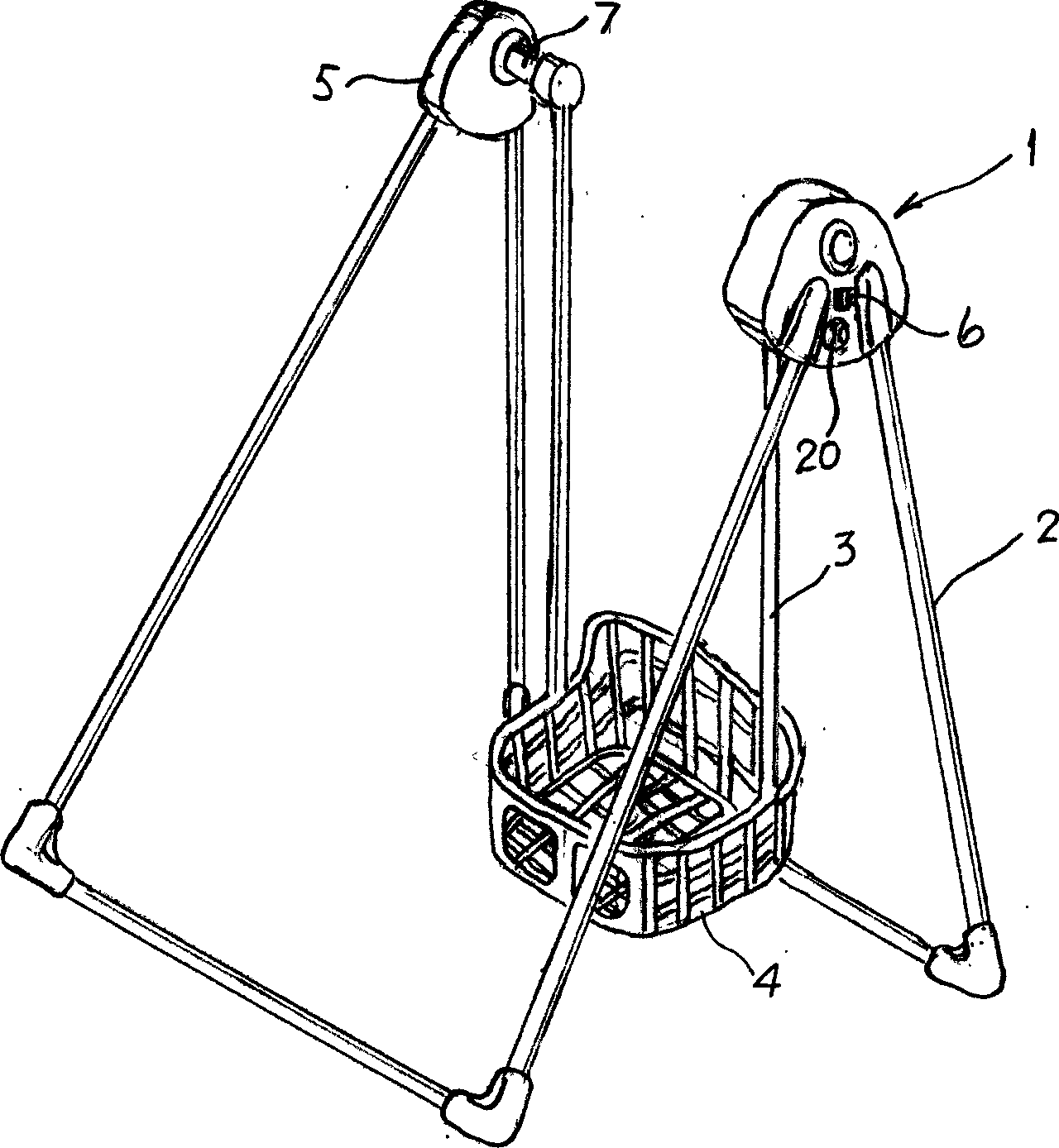
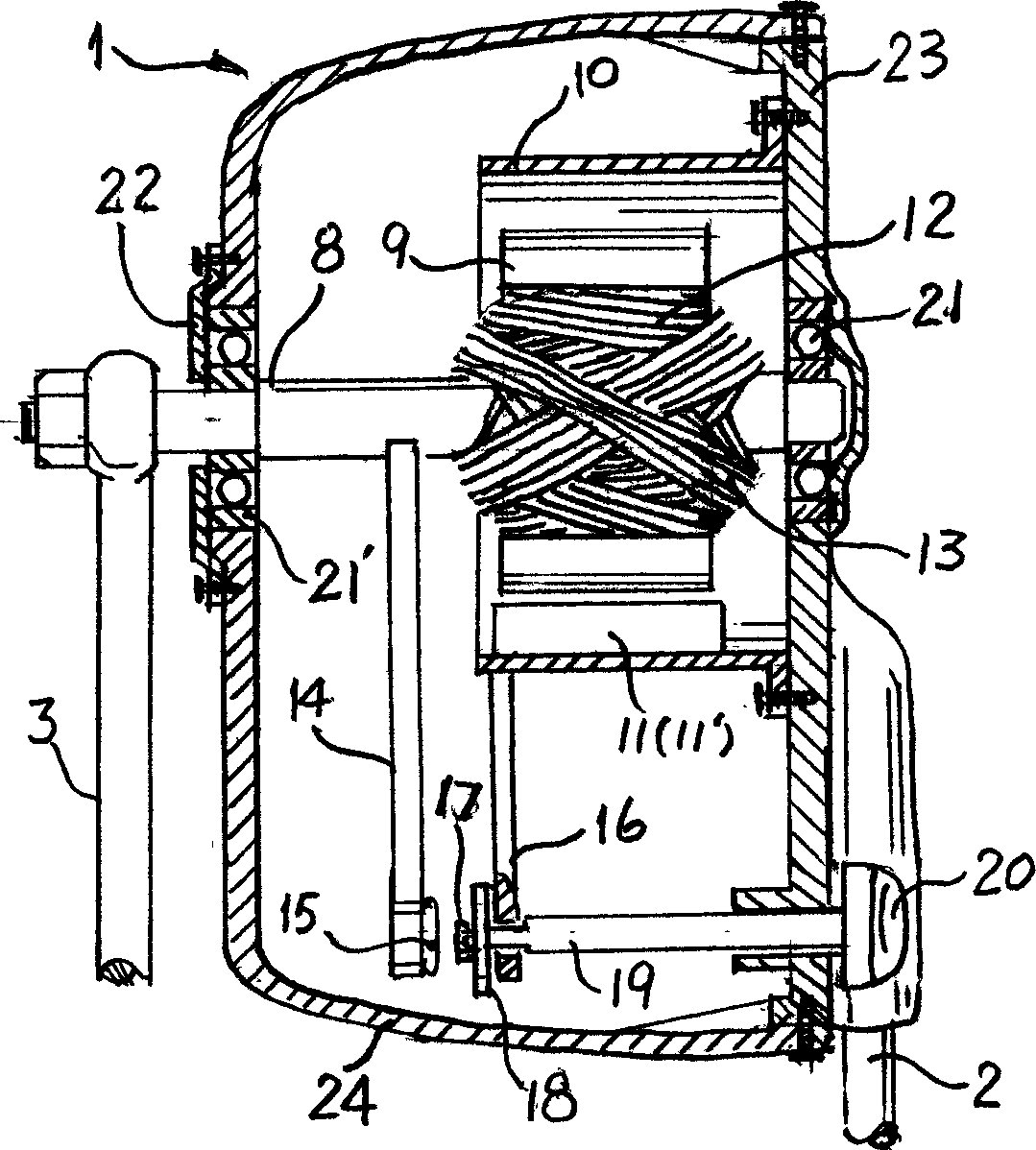
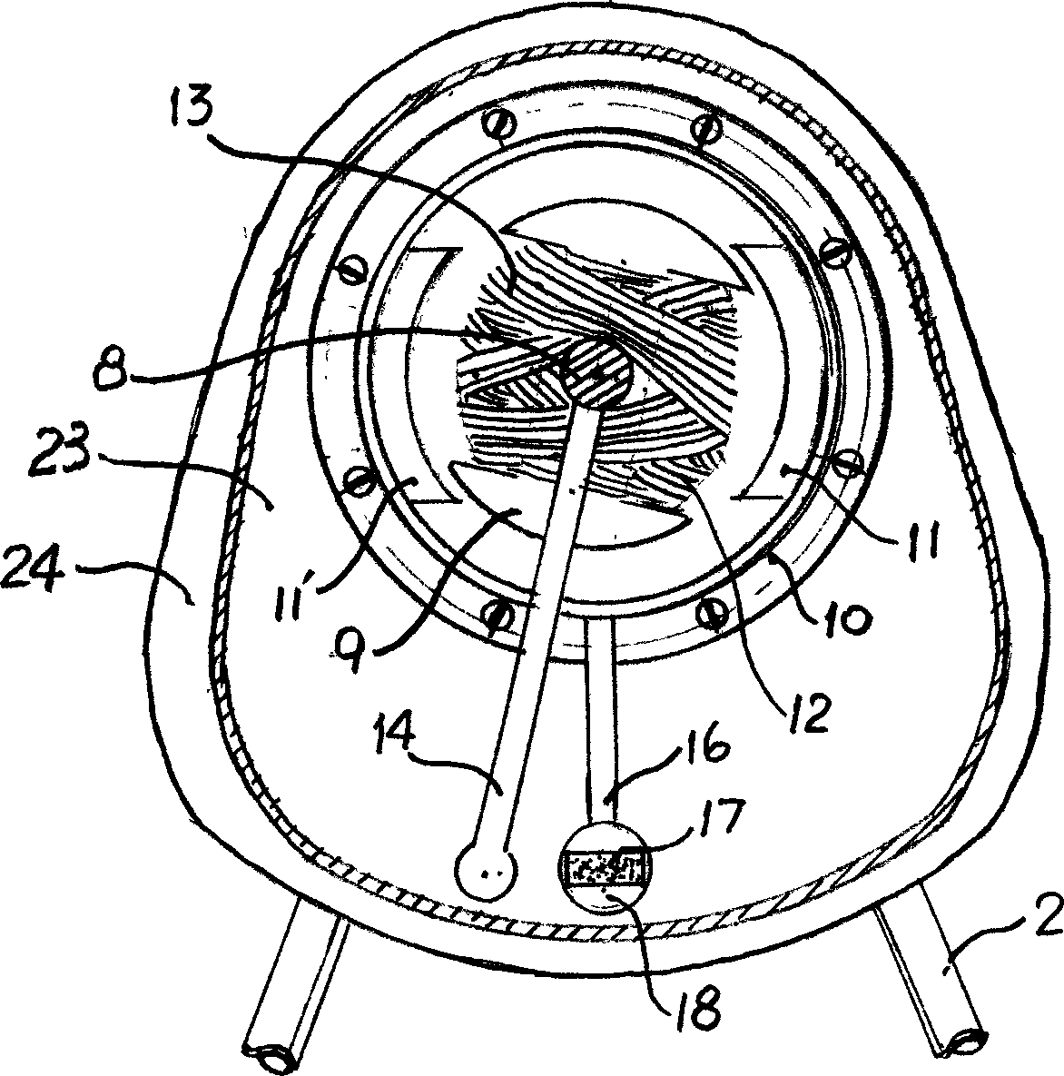
[0040] figure 1 Shown is a baby bouncer with a disconnected horizontal axis. exist figure 1 Among them, the bottom ends of the two cantilevers (3) of the oscillating body are connected with the rocking chair (4), and the top ends are respectively connected with the rotating shaft in the driving mechanism (1) at one end and the driven shaft (7) at the other end. The four supporting legs of (2) respectively support the driving mechanism (1) and the driven bearing in the driven bearing box (5) at a certain height position. The start button (6) and the position adjustment knob (20) are installed on the fixed plate of the drive mechanism (1) respectively. Driven by the driving mechanism (1), the cantilever (3) drives the rocking chair (4) to swing back and forth.

[0041] from figure 2 with image 3 The structural relationship of the drive mechanism can be seen. The inner layer of the dumbbell-shaped iron core (9) of the rotor is wound with the working coil (12), the outer l...

Embodiment 2

[0046] Figure 4 What is shown is a photoelectric switch structure that can continuously adjust the location range. The other mechanical structures and working principles of the driving mechanism using this photoelectric switch structure are basically similar to those shown in Embodiment 1. The difference is that the reed switch of the zone control unit in embodiment 1 is used Figure 4The photoelectric switch shown can continuously adjust the position range instead. This photoelectric switch is made up of two parts, namely the photoelectric switch that can rotate with the rotating shaft and the relatively fixed adjustable light blocking mechanism. The through-beam photoelectric switch (25) fixed on the connecting piece (14) is a slot-type photoelectric switch commonly used in industry, and its interior is mainly composed of separate light emitters and light receivers. When there is an obstruction, the light receiver receives the light from the light emitter, and the photoel...


PUM


Abstract

Driving mechanism for rocking chair, rocking bed and swing is driven by electromagnetism. Permanent magnet is as stator, and electromagnetic core wrapped by operating coil and induction coil is as rotor. Induced current from induction coil and location signal of rotor control current direction of operation coil and operated location, making magnetic poles of rotor be changed properly so as to obtain moment in direction identical to rotation direction alternately and in impulse. The said moment brings along swing body, which is connected to axis of rotation of rotor, rocking automatically.

Description

technical field [0001] The invention relates to a method for driving an oscillating body and an electromagnetic driving mechanism. More precisely, the present invention relates to a driving method and an electromagnetic driving mechanism that can make rocking chairs, cradles, swings, wooden horses, toys and other similar oscillating bodies for babies or children automatically sway through electromagnetic force. Background technique [0002] People have always hoped to have such a mechanism that uses electric energy as power to drive baby or children's rocking chairs, rocking beds, swings, wooden horses, toys and other similar swinging bodies (hereinafter referred to as swinging bodies), which can be made like swinging bodies without people pushing and pulling. Swing freely like a swing. The main structure of this oscillating body is usually two (in some cases, it can be one) cantilever suspended on the horizontal axis. Can be other support methods), the horizontal axis is ...

Claims


Application Information

Patent Timeline
Patent Type & Authority Applications(China)
IPC IPC(8): H02K33/18H02P6/00H02P7/00
Inventor 张国瑞
Owner 张国瑞
Learn More