Near field reader antenna and antenna array used for unmanned checkout platform

A reader and antenna technology, applied in the field of RFID systems, can solve the problem of short reading distance in the near field, and achieve the effect of low gain in the far field, easy processing, and reducing interference

Pending Publication Date: 2018-03-13
SUZHOU YOUHAN INFORMATION TECH CO LTD
View PDF0 Cites 5 Cited by
  • Summary
  • Abstract
  • Description
  • Claims
  • Application Information

AI Technical Summary

Problems solved by technology

[0008] In order to solve the problem that the near-field reading distance of magnetic field coupling is too short in the prior art, a near-field reader antenna and ant

Method used


Image

  • Near field reader antenna and antenna array used for unmanned checkout platform
  • Near field reader antenna and antenna array used for unmanned checkout platform
  • Near field reader antenna and antenna array used for unmanned checkout platform

Examples


Embodiment 1

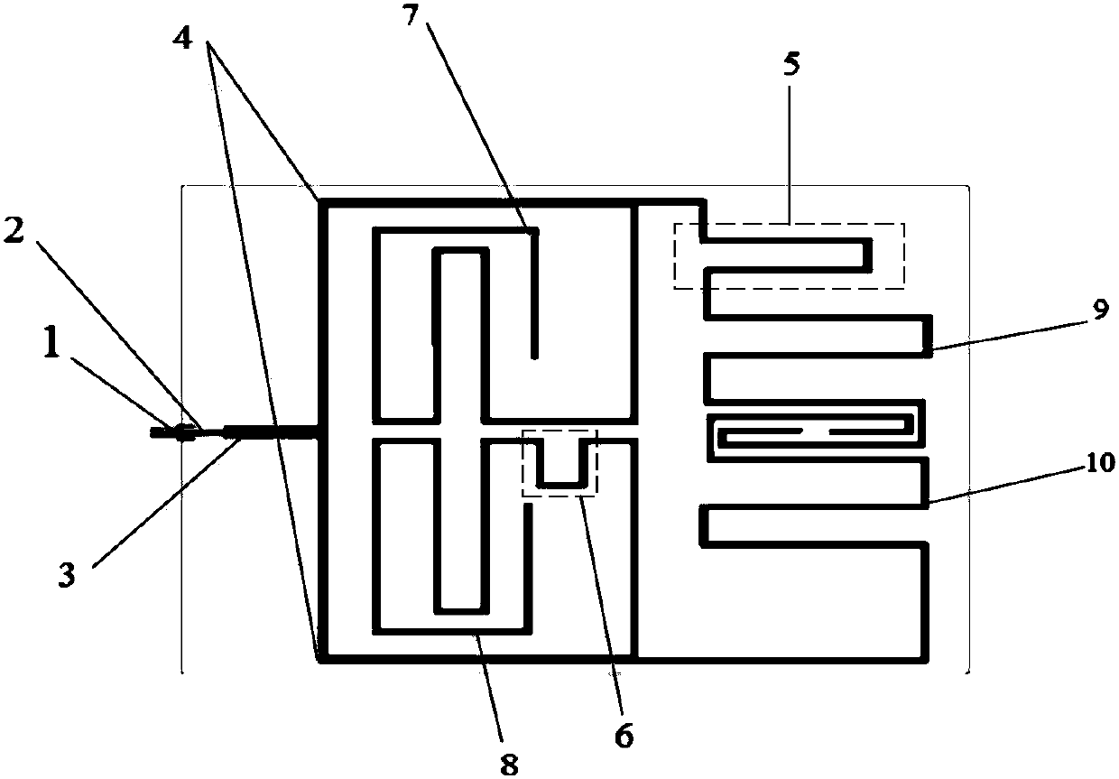
[0041] like figure 1 As shown, the near-field reader antenna proposed by the present invention for an unmanned cashier platform includes an SMA connector 1, a feed port 2, an antenna matching branch 3, a power distribution branch 4, an antenna microstrip radiation branch, and a phase-shifting branch; The antenna feed port adopts an SMA connector 1 to be directly connected to one end of the feed port 2, and the other end is connected to the antenna matching branch 3; the antenna matching branch 3 is connected to the power divider 4 of the antenna, and the antenna power divider 4 is connected to the antenna microstrip radiation The branches are connected. Feed port 2 is a 50 ohm microstrip line. like figure 2As shown, the antenna has three layers in total, the top layer 11 is provided with the structure as claimed in claim 1, the middle layer is a dielectric layer 12, and the bottom layer is a ground layer 13. The material of the microstrip structure such as the antenna feed...

Embodiment 2

[0044] UHF near field RFID reader antenna for unmanned cashier platform. figure 1 It is a schematic diagram of the top-level plan structure of the UHF near-field RFID reader antenna. Such as figure 1 As shown, the antenna consists of SMA connector 1, feed port 2, antenna matching branch 3, power distribution branch 4, left phase shifting branch 5, right phase shifting branch 6, and antenna microstrip radiation branch. figure 2 It is a side schematic diagram of the UHF near-field RFID reader antenna, such as figure 2 As shown, the antenna has three layers, the top layer 11, the dielectric layer 12, and the ground layer 13. An SMA connector 1 is used to directly connect the antenna feeder to the 50-ohm microstrip line 2, so that the feeder and the antenna are well matched. Strong and easy to solder. One end of the 50 ohm microstrip line 2 is welded with an SMA head, and the other end is connected to the matching stub 3 . The antenna matching stub 3 is connected to the powe...

Embodiment 3

[0050] The antenna radiation structure is composed of two phase shifting structures and four microstrip line serpentine structures. In the four-section microstrip serpentine structure, two microstrip serpentine structures adopt bilateral symmetry, and the other two microstrip serpentine structures adopt approximately mirror images on both sides, and the path length of the four microstrip lines is are the same, and the ends of the four serpentine microstrip structures are all in an open state.

[0051] The four sections of antenna microstrip radiation branches are respectively upper left microstrip line 7, left lower microstrip line 8, right upper microstrip line 9, right lower microstrip line 10, left upper microstrip line 7 and left lower microstrip line 8, which are arranged symmetrically up and down, The upper right microstrip line 9 and the lower right microstrip line 10 are symmetrically arranged up and down;

[0052] The upper left microstrip line 7 and the lower left m...


PUM


Abstract

The invention discloses a near-field reader antenna and an antenna array for an unmanned cash register platform. Its antenna radiation structure includes antenna microstrip radiation branches and phase-shifting branches; antenna microstrip radiation branches include antenna microstrip lines set in the vertical direction and antenna microstrip lines set in the horizontal direction, forming a serpentine structure, adjusting the level of the microstrip line and The vertical length makes the current flow direction in the local vertical direction the same as the current flow direction in the local horizontal direction; phase-shifting stubs are inserted in the part of the same flow direction of the antenna microstrip line, so that the space height of the current in the same direction is the same, and the electric field in the near field area is realized. More polarization directions to avoid near-field tag misreading. The present invention can avoid the misreading of far-field tags, and also reduce the interference of other systems to the unmanned RFID system; it can read coil-type tag antennas, and can also read dipole-like tag antennas, and the antennas are more flexible sex.

Description

technical field [0001] The present invention relates to the technical field of an RFID (Radio Frequency Identification, radio frequency identification) system, in particular to an RFID near-field reader antenna and an antenna array for an unmanned cash register platform. Background technique [0002] Radio Frequency Identification (RFID) technology is a technology that uses radio frequency signals to realize automatic identification and wireless data transmission through backscattering or electromagnetic field coupling. The reader antenna is an indispensable part of the RFID system, and the performance of the antenna directly affects the performance of the entire system. RFID technology is an indispensable and important part of the Internet of Things, widely used in libraries, access control systems, food safety traceability and other fields. Furthermore, the integration of RFID systems and mobile terminals such as mobile phones can realize mobile Internet applications such...

Claims


Application Information

Patent Timeline
IPC IPC(8): H01Q1/22H01Q1/38H01Q1/50H01Q21/00
CPCH01Q1/38H01Q1/2225H01Q1/50H01Q21/00
Inventor 何赛灵李俊龙刘辉
Owner SUZHOU YOUHAN INFORMATION TECH CO LTD
Why Eureka
Try Eureka