Rubber tube sleeving method and system for rod piece

A pipe system and rod technology, applied in the field of mechanical installation, can solve the problem of inconvenient fitting of rubber hose on the rod

Active Publication Date: 2018-03-16
LENS TECH CHANGSHA
View PDF2 Cites 4 Cited by
  • Summary
  • Abstract
  • Description
  • Claims
  • Application Information

AI Technical Summary

Problems solved by technology

[0004] In view of this, the first object of the present invention is to provide a method for covering rubber hoses on rods, which can effectively solve the inconvenient problem of covering rubber hoses on rods. The second object of the present invention is to provide A rod with rubber hose system adopting the above rod with rubber hose method

Method used


Image

  • Rubber tube sleeving method and system for rod piece
  • Rubber tube sleeving method and system for rod piece

Examples


Embodiment Construction

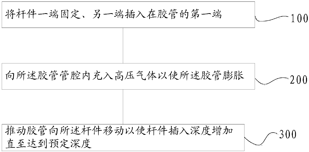
[0033] The embodiment of the present invention discloses a method for covering a rubber hose on a rod to effectively solve the problem of inconvenient putting a rubber hose on a rod.

[0034] The following will clearly and completely describe the technical solutions in the embodiments of the present invention with reference to the accompanying drawings in the embodiments of the present invention. Obviously, the described embodiments are only some, not all, embodiments of the present invention. Based on the embodiments of the present invention, all other embodiments obtained by persons of ordinary skill in the art without making creative efforts belong to the protection scope of the present invention.

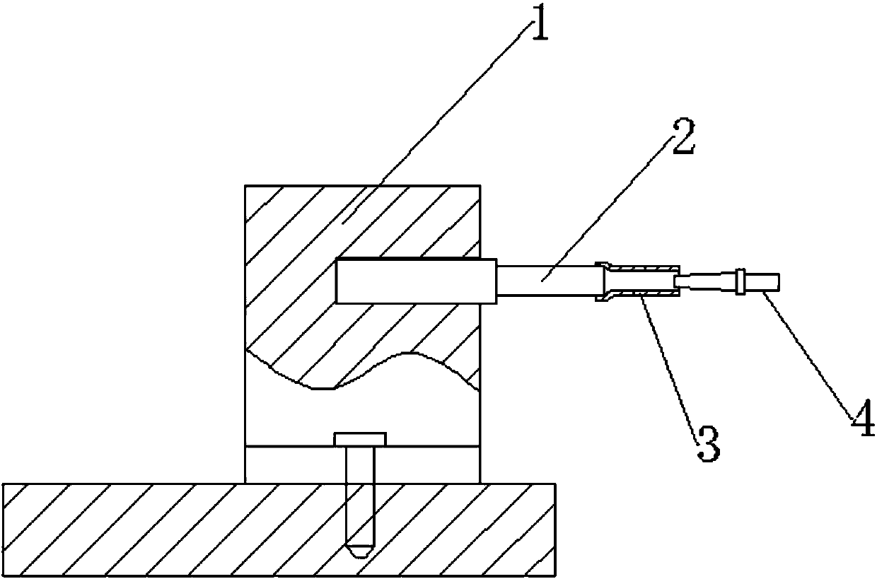
[0035] see Figure 1-Figure 2 , figure 1 Schematic diagram of the structure of the rod-mounted rubber hose method provided by the embodiment of the present invention; figure 2 A structural schematic diagram of a rod-in-a-hose system provided by an embodiment of the present in...


PUM


Abstract

The invention discloses a rubber tube sleeving method for a rod piece. The method includes the steps that one end of the rod piece is fixed and the other end of the rod piece is inserted into the first end of a rubber tube; a tube cavity of the rubber tube is filled with high-pressure gas so that the rubber tube can be expanded; and the rubber tube is pushed to move towards the rod piece, and theinserting depth of the rod piece is increased until a preset depth is reached. By adoption of the rubber tube sleeving method for the rod piece, the rubber tube can be expanded through the high-pressure gas, and therefore the friction force between the rubber tube and the rod piece in the moving process of the rubber tube is greatly reduced, and pushing of the rubber tube to move can be greatly facilitated; and meanwhile applied force is small and operation is quite easy. Hence, the rubber tube sleeving speed can be greatly increased through the rubber tube sleeving method for the rod piece, and operation is convenient. The invention further discloses a rubber tube sleeving system for the rod piece using the rubber tube sleeving method for the rod piece.

Description

technical field [0001] The present invention relates to the technical field of mechanical installation, and more specifically, relates to a rod-mounted rubber hose method, and also relates to a rod-mounted rubber hose system adopting the above-mentioned rod-mounted rubber hose method. Background technique [0002] Polishing rods are mainly used for precision polishing of inner holes and outer circles of materials such as glass and gemstones. Small, and set on the surface of the substrate, the elastic tension generated by the expansion of the inner diameter of the hose makes it fit tightly on the surface of the substrate, so as to ensure that the hose will not fall off or slide from the substrate. However, it is not easy to evenly fit the rubber hose with an inner diameter smaller than that of the substrate on the substrate. If the rubber hose is placed on the substrate by hand, since the inner diameter of the rubber hose is smaller than that of the substrate, the substrate i...

Claims


Application Information

Patent Timeline
Patent Type & Authority Applications(China)
IPC IPC(8): B29C63/42
CPCB29C63/42
Inventor 饶桥兵成湘宁
Owner LENS TECH CHANGSHA
Why Eureka
Try Eureka