Lifting mechanism and disinfection equipment

A technology of lifting mechanism and disinfection equipment, which is applied in the direction of disinfection, lifting racks, sanitary equipment for toilets, etc. It can solve the problems that unfavorable users use the disinfection cabinet and the stability of the lifting mechanism cannot be fully guaranteed, so as to achieve reliable lifting , to avoid long hours of work, to avoid the effect of potential safety hazards

Active Publication Date: 2018-03-16
GUANGDONG MIDEA KITCHEN APPLIANCES MFG CO LTD +1
View PDF5 Cites 8 Cited by
  • Summary
  • Abstract
  • Description
  • Claims
  • Application Information

AI Technical Summary

Problems solved by technology

[0002] Since the cabinet in the home kitchen is lower than the countertop of the kitchen table, when the disinfection cabinet is placed in the cabinet or on the ground, the user needs to bend down or squat down when accessing the tableware, which is not conducive to the use of the disinfection cabinet by the user.
In order to solve the above problems, people think of setting up a lifting structure, but when the existing lifting structure is raised to a preset position, a driving mechanism is required to limit the position of the lifting structure, so that the stability of the lifting mechanism cannot be fully guaranteed.

Method used


Image

  • Lifting mechanism and disinfection equipment
  • Lifting mechanism and disinfection equipment
  • Lifting mechanism and disinfection equipment

Examples


Embodiment Construction

[0065] The following will clearly and completely describe the technical solutions in the embodiments of the present invention with reference to the accompanying drawings in the embodiments of the present invention. Obviously, the described embodiments are only part of the embodiments of the present invention, not all of them. Based on the embodiments of the present invention, all other embodiments obtained by persons of ordinary skill in the art without creative efforts fall within the protection scope of the present invention.

[0066] It should be noted that all directional indications (such as up, down, left, right, front, back...) in the embodiments of the present invention are only used to explain the relationship between the components in a certain posture (as shown in the accompanying drawings). Relative positional relationship, movement conditions, etc., if the specific posture changes, the directional indication will also change accordingly.

[0067] In addition, the ...


PUM


Abstract

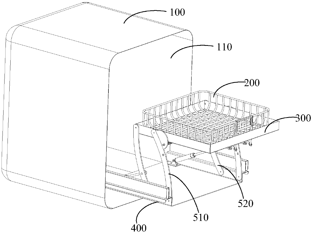
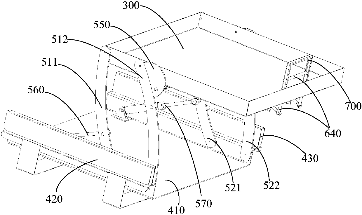
The invention discloses a lifting mechanism and disinfection equipment. The lifting mechanism comprises a containing frame provided with containing space for containing to-be-disinfected objects, a base located below the containing frame, a first connecting rod assembly, a second connecting rod assembly, a locating part and a locking assembly. One end of the first connecting rod assembly is rotationally connected with the base, and the other end of the first connecting rod assembly is rotationally connected with the containing frame. The second connecting rod assembly is opposite to the firstconnecting rod assembly, one end of the second connecting rod assembly is rotationally connected with the base, and the other end of the second connecting rod assembly is rotationally connected with the containing frame so that the containing frame can ascend and descend along with swing of the first connecting rod assembly and the second connecting rod assembly. The locating part is arranged on the first connecting rod assembly and/or the second connecting rod assembly and is provided with a limiting structure. The locking assembly is arranged at the position, corresponding to the locating part, of the bottom of the containing frame. When the locating part deflects to the preset position relative to the containing frame along with swing of the first connecting rod assembly and/or the second connecting rod assembly, the locking assembly and the limiting structure are locked. According to the technical scheme, the stability of the lifting mechanism can be improved easily.

Description

technical field [0001] The invention relates to the technical field of disinfection equipment, in particular to a lifting mechanism and disinfection equipment. Background technique [0002] Because the cabinet in the home kitchen is lower than the countertop of the kitchen table, when the disinfection cabinet is placed in the cabinet or on the ground, the user needs to bend over or squat when accessing the tableware, which is not conducive to the use of the disinfection cabinet by the user. In order to solve the above problems, people think of setting up a lifting structure, but when the existing lifting structure is raised to a preset position, a driving mechanism is required to limit the position of the lifting structure, so that the stability of the lifting mechanism cannot be fully guaranteed. Contents of the invention [0003] The main purpose of the present invention is to provide a lifting mechanism, aiming at improving the stability of the lifting mechanism while f...

Claims


Application Information

Patent Timeline
Patent Type & Authority Applications(China)
IPC IPC(8): B66F7/06B66F7/08B66F7/28A61L2/26
CPCA61L2/26B66F7/0641B66F7/085B66F7/28
Inventor 贾志强胡永王佳新林文灿季俊生
Owner GUANGDONG MIDEA KITCHEN APPLIANCES MFG CO LTD
Why Eureka
Try Eureka