Supercharge Your Innovation With Domain-Expert AI Agents!

Anti-burnout LED drive

A technology of LED drive and LED lamps, which is applied in the direction of electrical components, electroluminescent light sources, lighting devices, etc., can solve the problems of burning out lamps, concentrating to another lamp, loss, etc., and achieve the effect of avoiding burnout

Inactive Publication Date: 2018-03-16
广东科隆达健康照明智能科技有限公司
View PDF0 Cites 0 Cited by
  • Summary
  • Abstract
  • Description
  • Claims
  • Application Information

AI Technical Summary

Problems solved by technology

In order to reduce costs and facilitate control, two lamps often share a constant current drive power supply, and the two lamps share the output current of the constant current drive power supply equally. Break another light fixture, causing additional damage

Method used


Image

  • Anti-burnout LED drive

Examples


Embodiment Construction

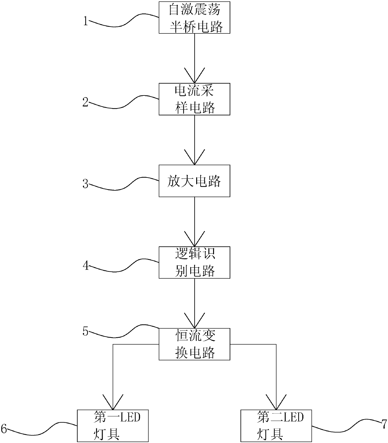
[0012] figure 1 is the circuit block diagram of the present invention, such as figure 1 As shown, an anti-burnout LED driver includes a self-oscillating half-bridge circuit 1, a current sampling circuit 2, an amplifier circuit 3, a logic identification circuit 4, a constant current conversion circuit 5, a first LED lamp 6 and a second LED lamp 7. The self-excited oscillation half-bridge circuit 1 is connected to the current sampling circuit 2, the current sampling circuit 2 is connected to the amplifying circuit 3, the amplifying circuit 3 is connected to the logic identification circuit 4, and the logic identification circuit 4 is connected to the constant current conversion circuit 5, the constant current The conversion circuit 5 is connected to the first LED lamp 6 and the second LED lamp 7 respectively. The logic identification circuit 4 provided in the present invention can effectively identify whether two LED lamps are working at the same time or one LED lamp is working...


PUM


Abstract

The invention discloses an anti-burnout LED drive which includes a self-excited oscillation half-bridge circuit, a current sampling circuit, an amplification circuit, a logic identification circuit, aconstant current transformation circuit, a first LED lamp and a second LED lamp. The self-excited oscillation half-bridge circuit is connected to the current sampling circuit. The current sampling circuit is connected to the amplification circuit. The amplification circuit is connected to the logic identification circuit. The logic identification circuit is connected to the constant current transformation circuit. The constant current transformation circuit is connected to the first LED lamp and the second LED lamp. The logic identification circuit of the invention can effectively identify whether the two LED lamps work at the same time or one LED lamp works alone. If the two LED lamps work at the same time, the constant current transformation circuit outputs a large current under control. If one LED lamp works alone, the constant current transformation circuit outputs a small current under control. Thus, the LED lamps can be prevented from being burned out.

Description

technical field [0001] The invention relates to an LED driver, in particular to an anti-burnout LED driver. Background technique [0002] LED lighting fixtures are deeply loved by consumers because of their advantages of energy saving and high light efficiency. In order to reduce costs and facilitate control, two lamps often share a constant current drive power supply, and the two lamps share the output current of the constant current drive power supply equally. Break another light fixture, causing additional losses. Contents of the invention [0003] In order to solve the above problems, the object of the present invention is to provide an anti-burnout LED driver. [0004] The technical solution adopted by the present invention to solve the problem is: an anti-burnout LED drive, including a self-excited oscillation half-bridge circuit, a current sampling circuit, an amplifier circuit, a logic identification circuit, a constant current conversion circuit, the first LED l...

Claims


Application Information

Patent Timeline
Patent Type & Authority Applications(China)
IPC IPC(8): H05B33/08H05B44/00
CPCH05B45/50Y02B20/30
Inventor 陈文球
Owner 广东科隆达健康照明智能科技有限公司
Features
  • R&D
  • Intellectual Property
  • Life Sciences
  • Materials
  • Tech Scout
  • Unparalleled Data Quality
  • Higher Quality Content
  • 60% Fewer Hallucinations
Learn More