Steel plate bending device
A kind of equipment and steel plate technology, applied in the field of bending equipment, can solve the problems of hurting people's bodies, time-consuming, labor-intensive, dangerous, etc., and achieve the effects of accurate bending, simple manufacturing, and low manufacturing cost
- Summary
- Abstract
- Description
- Claims
- Application Information
AI Technical Summary
Problems solved by technology
Method used
Image
Examples
Embodiment 1
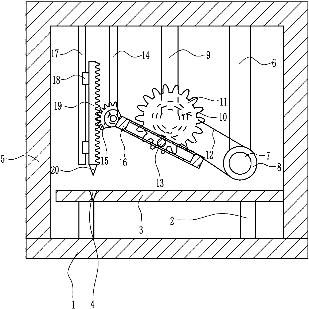
[0024] A steel plate bending equipment, such as Figure 1-4 As shown, it includes a base 1, a table foot 2, a table board 3, a frame 5, a first support 6, a motor 7, a first pulley 8, a second support 9, a second pulley 10, a first gear 11, Belt 12, fixed block 13, the third support 14, sector gear 15, connecting rod 16, slide rail 17, slide block 18, tooth bar 19 and taper head 20 are fixed with table foot 2 symmetrically on base 1 left and right, in A table board 3 is fixedly connected above the two table legs 2, a first groove 4 is provided on the upper left side of the table board 3, a frame 5 is welded on the top of the base 1, and a fixed connection is fixed on the inside of the frame 5 A first support 6 is arranged, and a motor 7 is arranged on the first support 6, a first pulley 8 is connected on the output shaft of the motor 7, and a second support 9 is fixedly connected to the top of the frame 5 inside, and the second support 9 is located on the left side of the fir...
Embodiment 2
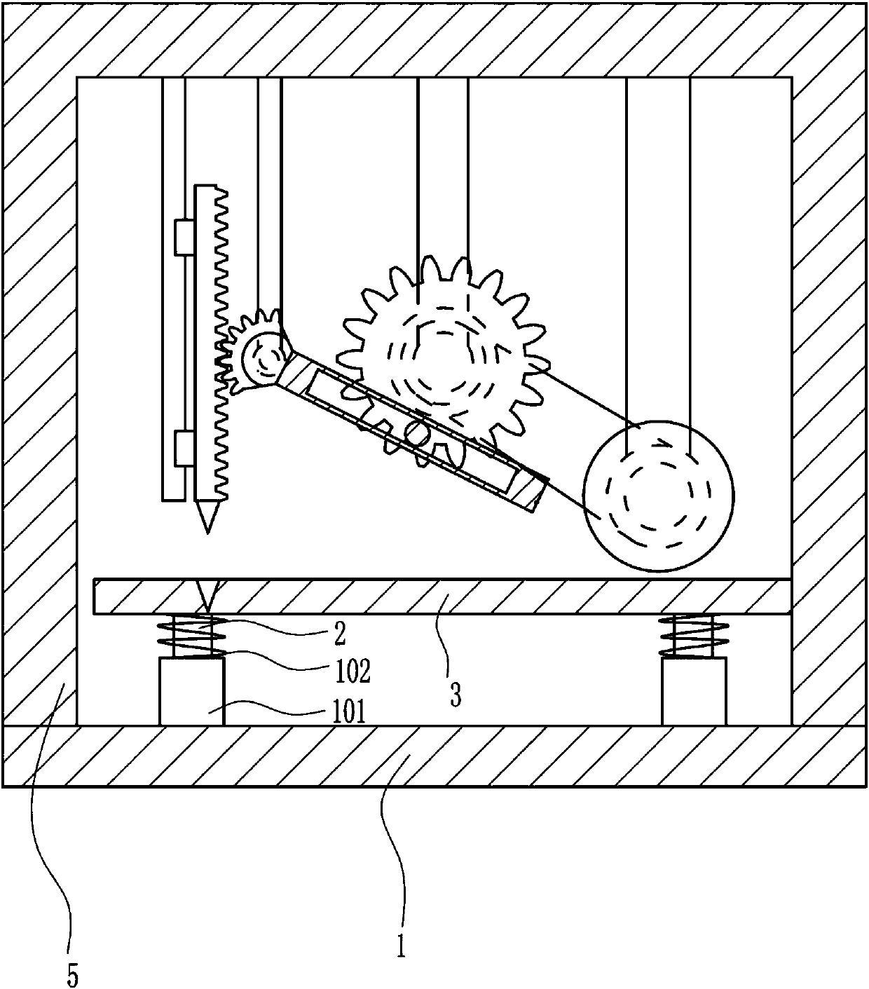
[0026] A steel plate bending equipment, such as Figure 1-4 As shown, it includes a base 1, a table foot 2, a table board 3, a frame 5, a first support 6, a motor 7, a first pulley 8, a second support 9, a second pulley 10, a first gear 11, Belt 12, fixed block 13, the third support 14, sector gear 15, connecting rod 16, slide rail 17, slide block 18, tooth bar 19 and taper head 20 are fixed with table foot 2 symmetrically on base 1 left and right, in A table board 3 is fixedly connected above the two table legs 2, a first groove 4 is provided on the upper left side of the table board 3, a frame 5 is welded on the top of the base 1, and a fixed connection is fixed on the inside of the frame 5 A first support 6 is arranged, and a motor 7 is arranged on the first support 6, a first pulley 8 is connected on the output shaft of the motor 7, and a second support 9 is fixedly connected to the top of the frame 5 inside, and the second support 9 is located on the left side of the fir...
Embodiment 3
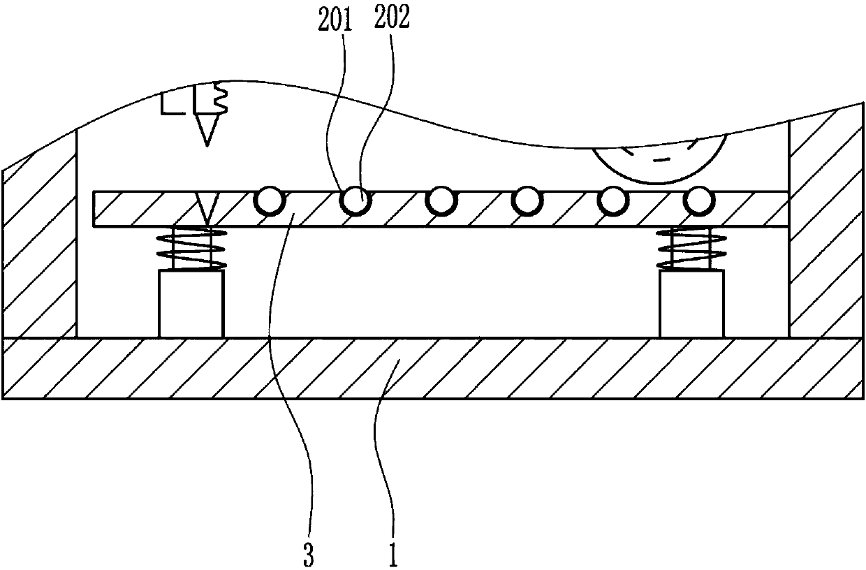
[0029] A steel plate bending equipment, such as Figure 1-4 As shown, it includes a base 1, a table foot 2, a table board 3, a frame 5, a first support 6, a motor 7, a first pulley 8, a second support 9, a second pulley 10, a first gear 11, Belt 12, fixed block 13, the third support 14, sector gear 15, connecting rod 16, slide rail 17, slide block 18, tooth bar 19 and taper head 20 are fixed with table foot 2 symmetrically on base 1 left and right, in A table board 3 is fixedly connected above the two table legs 2, a first groove 4 is provided on the upper left side of the table board 3, a frame 5 is welded on the top of the base 1, and a fixed connection is fixed on the inside of the frame 5 A first support 6 is arranged, and a motor 7 is arranged on the first support 6, a first pulley 8 is connected on the output shaft of the motor 7, and a second support 9 is fixedly connected to the top of the frame 5 inside, and the second support 9 is located on the left side of the fir...
PUM
 Abstract
Description
Claims
Application Information
 - R&D
- Intellectual Property
- Life Sciences
- Materials
- Tech Scout
- Unparalleled Data Quality
- Higher Quality Content
- 60% Fewer Hallucinations
Browse by: Latest US Patents, China's latest patents, Technical Efficacy Thesaurus, Application Domain, Technology Topic, Popular Technical Reports.
© 2025 PatSnap. All rights reserved.Legal|Privacy policy|Modern Slavery Act Transparency Statement|Sitemap|About US| Contact US: help@patsnap.com


