Narrow beam H-shaped slot-coupling microstrip paster array antenna

A microstrip patch and array antenna technology, applied in the field of antennas, can solve the problem of narrow bandwidth of microstrip antennas, and achieve the effects of improving isolation, improving circular polarization characteristics, and expanding circular polarization bandwidth.

Inactive Publication Date: 2018-03-23
XIDIAN UNIV
View PDF4 Cites 15 Cited by
  • Summary
  • Abstract
  • Description
  • Claims
  • Application Information

AI Technical Summary

Problems solved by technology

The microstrip patch antenna is a resonant antenna, and the conventional microstrip antenna has a narrow bandwidth (less than 3%)

Method used


Image

  • Narrow beam H-shaped slot-coupling microstrip paster array antenna
  • Narrow beam H-shaped slot-coupling microstrip paster array antenna
  • Narrow beam H-shaped slot-coupling microstrip paster array antenna

Examples


Embodiment Construction

[0039] Below in conjunction with embodiment accompanying drawing, the present invention will be further described:

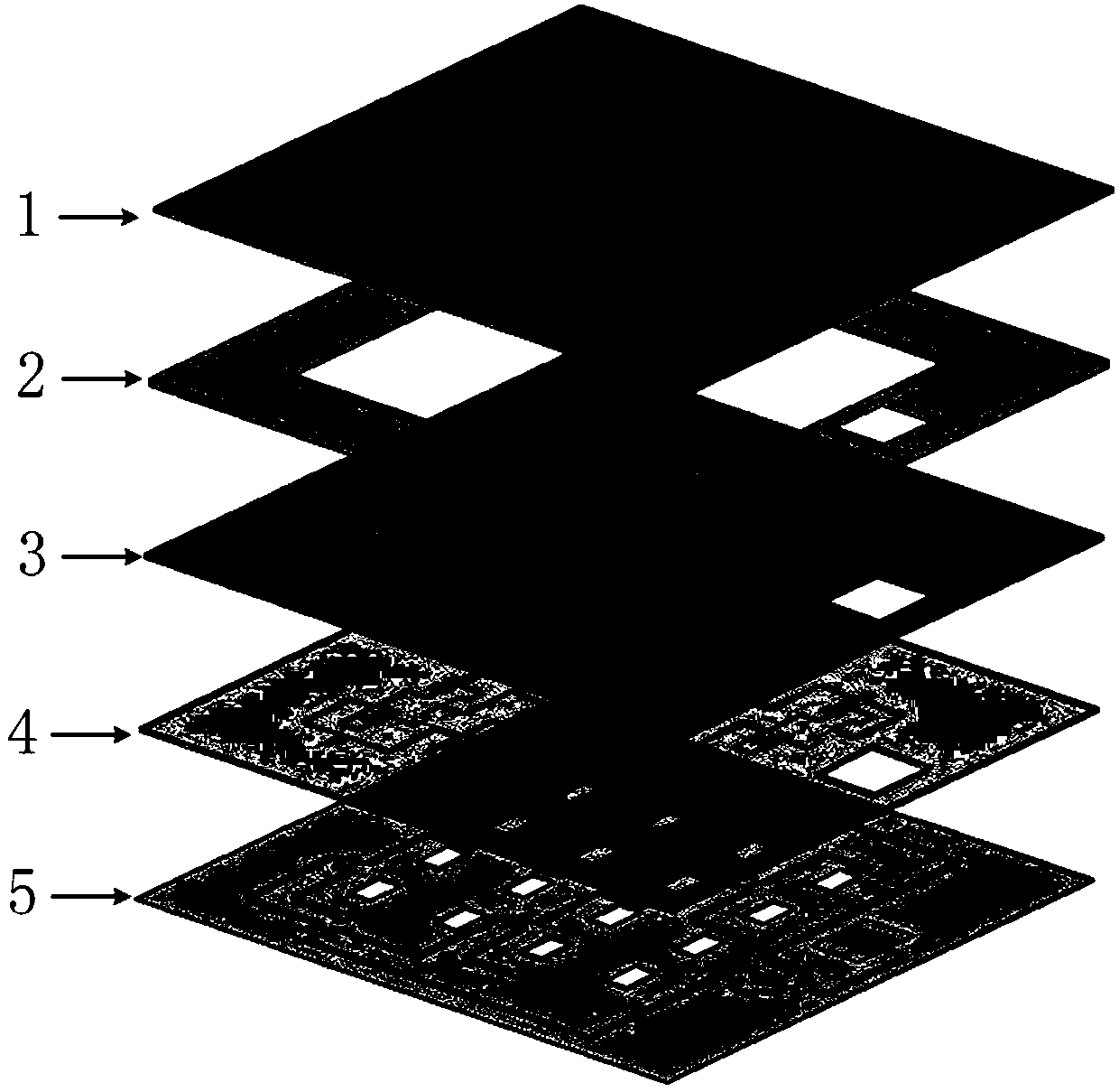
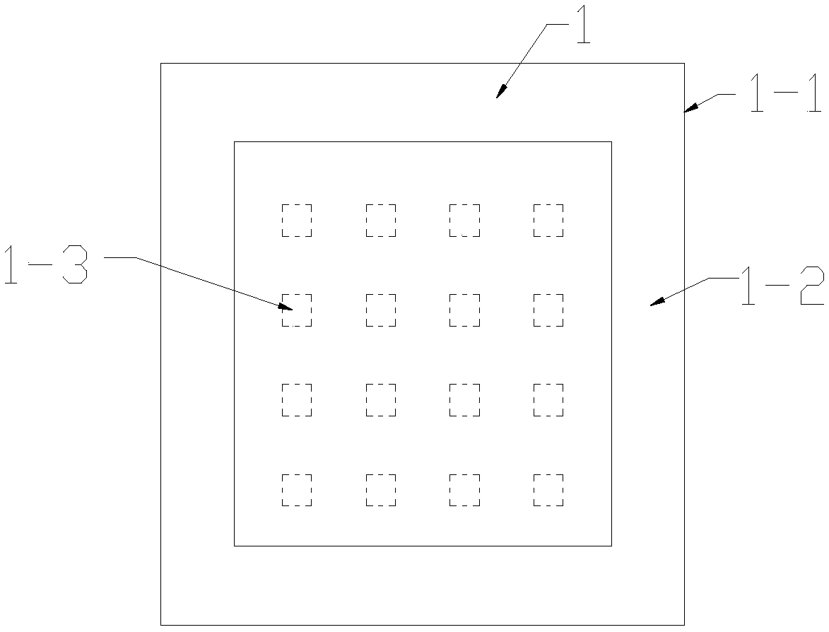
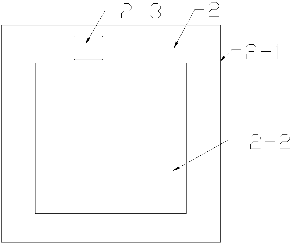
[0040] Such as figure 1As shown, a narrow-beam H-shaped slot-coupled microstrip patch array antenna is characterized in that it includes a coupling patch layer 1, an air layer 2, a radiation patch layer 3, a stripline feed network layer 4, and a shifting patch layer. Phase feed network layer 5; wherein, stripline feed network layer 4 is a two-layer dielectric substrate, coupling patch layer 1, air layer 2, radiation patch layer 3, stripline feed network layer 4, phase shifting The feed network layer 5 is superimposed and connected sequentially. The total thickness of the coupling patch layer 1, the air layer 2, the radiation patch layer 3, the stripline feed network layer 4, and the phase-shift feed network layer 5 is 6.2 mm. The antenna is fixed with four screws around it.

[0041] The dielectric plate of the coupling patch layer 1 has a relative permittivity...


PUM


Abstract

The present invention relates to a narrow beam H-shaped slot-coupling microstrip paster array antenna. The antenna comprises a coupled paster layer, an air layer, a radiation paster layer, a strip line feed network layer and a phase shift feed network layer. The strip line feed network layer is a two-layer dielectric substrate, the coupled paster layer, the air layer, the radiation paster layer, the strip line feed network layer and the phase shift feed network layer are overlapped and connected in order, the overlapping total thickness of the coupled paster layer, the air layer, the radiationpaster layer, the strip line feed network layer and the phase shift feed network layer is 6.2mm, and the antenna is fixed by employing four screws at the periphery. The antenna provided by the invention has advantages of a high frequency band, a high gain and circular polarization.

Description

technical field [0001] The invention relates to the technical field of antennas, in particular to a narrow-beam H-shaped slot coupled microstrip patch array antenna. Background technique [0002] The antenna is the "choke point" of the wireless system. Its performance directly affects the performance index of the whole wireless system. For satellite communication systems, traditional engineering systems require antennas to be circularly polarized with high gain, and most of the currently disclosed antennas are aimed at narrowband systems. However, current satellite systems require antennas with high frequency band, high gain, and circular polarization characteristics. [0003] Microstrip patch antenna is a new type of antenna developed in the last 30 years. It has been widely used due to its light weight, good omnidirectional characteristics, and low cost. The microstrip patch antenna is a resonant antenna, and the conventional microstrip antenna has a narrow bandwidth (l...

Claims


Application Information

Patent Timeline
Patent Type & Authority Applications(China)
IPC IPC(8): H01Q1/36H01Q1/38H01Q1/50H01Q13/10H01Q23/00
CPCH01Q1/38H01Q1/36H01Q1/50H01Q13/106H01Q23/00
Inventor 张凡刘大桥李超张福顺
Owner XIDIAN UNIV
Why Eureka
Try Eureka