Broadband Base Station Antenna Based on Monopole Structure

A base station antenna and monopole technology, which is applied to antenna unit combinations, antennas, resonant antennas and other directions with different polarization directions, can solve the problems of complex structure of broadband base station antennas, achieve novel and simple structure, stable radiation performance, and reduce manufacturing costs. cost effect

Active Publication Date: 2021-02-02
XIDIAN UNIV
View PDF7 Cites 0 Cited by
  • Summary
  • Abstract
  • Description
  • Claims
  • Application Information

AI Technical Summary

Problems solved by technology

[0005] The purpose of the present invention is to solve the technical problems of complex broadband base station antenna structures in the prior art by proposing a broadband base station antenna based on a monopole structure in view of the deficiencies in the prior art above.

Method used


Image

  • Broadband Base Station Antenna Based on Monopole Structure
  • Broadband Base Station Antenna Based on Monopole Structure
  • Broadband Base Station Antenna Based on Monopole Structure

Examples


Embodiment 1

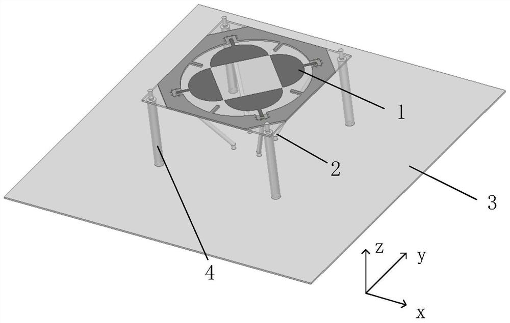
[0031] refer to figure 1 , figure 2 , image 3 and Figure 4 ;

[0032] 1. A broadband base station antenna based on a monopole structure, comprising a radiation structure 1, four identical coaxial feeders 2, a reflector 3, and a support column 4. The radiation structure 1 is composed of four identical monopoles Structure 1.1, a metal floor structure and a first dielectric board 1.3; the metal floor structure includes a first metal sticker 1.2.1 printed on the upper surface of the first dielectric board 1.3, and a second metal sticker printed on the lower surface Sheet 1.2.2, metal branch 1.2.3, metal through hole 1.2.5 and square slit 1.2.4, the metal through hole 1.2.5 is connected with the first metal patch 1.2.1 and the second metal patch 1.2.2 respectively interconnected; the four identical coaxial feeders 2 are located between the radiation structure 1 and the reflector 3; the reflector 3 includes a second dielectric plate 3.1 and a metal layer printed on the lower ...

Embodiment 2

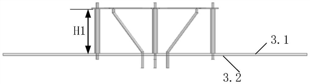
[0042] The first dielectric plate (1.3) and the second dielectric plate (3.1) are parallel to each other, and the distance between the first dielectric plate and the second dielectric plate is expressed as H1, wherein H1 is 35-40 mm. The H1 of the present invention is 35mm.

[0043] The four identical monopole structures (1.1) are respectively located on two diagonal lines of the first dielectric plate (1.3).

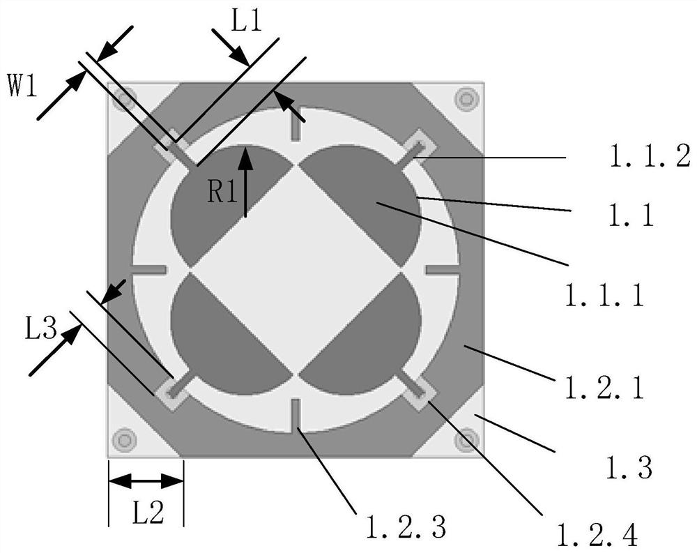
[0044] The radius of the semicircular patch (1.1.1) of each monopole (1.1) is represented as R1, the length of the short microstrip line (1.1.2) is represented as L1, and the width is represented as W1, wherein, R1 is 10-15mm, L1 is 5-8mm, and W1 is 1-3mm. In the present invention, R1 is 10 mm, L1 is 5 mm, and W1 is 1 mm.

[0045] The side length of the cut corner triangle of the floor structure (1.2) is denoted as L2, and the radius of the circular hole in the middle is denoted as R2, wherein L2 is 12-16 mm, and R2 is 28-35 mm. L2 in the present invention is 12mm, a...

Embodiment 3

[0050] The first dielectric plate (1.3) and the second dielectric plate (3.1) are parallel to each other, and the distance between the first dielectric plate and the second dielectric plate is expressed as H1, wherein H1 is 35-40 mm. H1 of the present invention is 40mm.

[0051] The four identical monopole structures (1.1) are respectively located on two diagonal lines of the first dielectric plate (1.3).

[0052] The radius of the semicircular patch (1.1.1) of each monopole (1.1) is represented as R1, the length of the short microstrip line (1.1.2) is represented as L1, and the width is represented as W1, wherein, R1 is 10-15mm, L1 is 5-8mm, and W1 is 1-3mm. In the present invention, R1 is 15 mm, L1 is 8 mm, and W1 is 3 mm.

[0053] The side length of the cut corner triangle of the floor structure (1.2) is denoted as L2, and the radius of the circular hole in the middle is denoted as R2, wherein L2 is 12-16 mm, and R2 is 28-35 mm. L2 in the present invention is 16mm, and R...


PUM


Abstract

The invention discloses a broadband base station antenna based on a monopole structure, which includes a radiation structure, four identical coaxial feeders, a reflector, and a support column. The radiation structure is composed of four identical monopole structures, metal The floor structure is composed of a first medium plate; the metal floor structure includes a first metal patch printed on the upper surface of the first medium plate, a second metal patch printed on the lower surface, metal branches, metal through holes and Square slits; the four identical monopole structures are composed of semicircular patches and short microstrip lines; the four identical monopole structures are located on the upper surface of the first dielectric plate, and about the center of the Z axis Symmetrical distribution; the short microstrip line extends to the position corresponding to the square slot. The present invention adopts four identical monopole structures as the main radiation patch, and the antenna structure is simple. The present invention can be used for base station antennas in IMT / 2G / 3G / 4G / LTE systems.

Description

technical field [0001] The invention belongs to the field of communication technology, and further relates to a broadband base station antenna based on a monopole structure in the field of electromagnetic field and microwave technology, which can be applied to base stations of IMT / 2G / 3G / 4G / LTE systems. Background technique [0002] With the development of wireless communication technology, modern mobile communication base station antennas are developing in the direction of broadband, miniaturization, multi-standard system coexistence and low cost. As a crucial part of information transmission and reception in mobile communication systems, research on miniaturized, broadband base station antennas, and multi-mode coexistence base station antennas has attracted much attention. At present, most base station antennas are developed for 2G / 3G / 4G / LTE systems, so base station antennas that can cover the 1.4-2.7GHz frequency band have received extensive attention, because the 1427-151...

Claims


Application Information

Patent Timeline
Patent Type & Authority Patents(China)
IPC IPC(8): H01Q1/38H01Q1/48H01Q1/50H01Q1/52H01Q9/30H01Q19/10H01Q21/00H01Q21/24
CPCH01Q1/38H01Q1/48H01Q1/50H01Q1/523H01Q9/30H01Q19/104H01Q21/0006H01Q21/0075H01Q21/24
Inventor 刘英黄盈黄铭初杨旭贾永涛
Owner XIDIAN UNIV
Why Eureka
Try Eureka