Brake pad drilling mold

A technology for drilling dies and brake pads, which is used in drilling dies for workpieces, metal processing, etc., can solve the problems of low drilling precision, insufficient fixing of brake pads, and lack of limit and guide devices for punching devices. Achieve the effect of facilitating subsequent installation and use, reducing the displacement of the brake pads, and improving the drilling accuracy

Inactive Publication Date: 2018-03-27
杨利人
View PDF0 Cites 1 Cited by
  • Summary
  • Abstract
  • Description
  • Claims
  • Application Information

AI Technical Summary

Problems solved by technology

Brake pads need to be drilled for the fixed installation of the brake pads. In the existing drilling process, the brake pads are not fixed firmly enough, and the brake pads are prone to shift during the drilling process, and the punching device lacks effective Limiting and guiding devices, resulting in lower drilling accuracy

Method used


Image

  • Brake pad drilling mold

Examples


Embodiment Construction

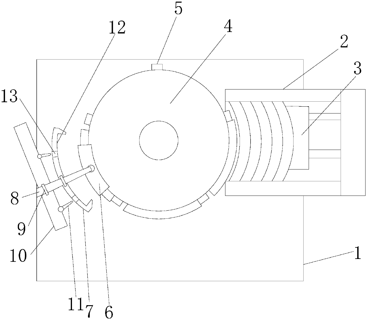
[0012] refer to figure 1 , a brake pad drilling mold of the present invention, comprising a base 1, a feeding trough 2, a pusher 3, a feeding turntable 4, a pushing protrusion 5, a pressing block 6, a limit card groove 7, a guide rail 8, an electric slide Block 9, movable substrate 10, drilling motor 11, the top of the base 1 is provided with a feeding chute 2, a pusher 3 is installed in the feeding chute 2, and a feeding turntable 4 is arranged on the left side of the feeding chute 2, so A plurality of pushing protrusions 5 are arranged on the feeding turntable 4, a pressing block 6 is arranged above the feeding turntable 4, and the pressing block 6 is installed below a guide rail 8, and the guide rail 8 is arranged on the left side of the feeding turntable 4 , the limit card slot 7 is installed on the guide rail 8 through the electric slider 9, the outer side of the limit card slot 7 is provided with a movable substrate 10, and the movable substrate 10 is provided with sever...


PUM


Abstract

The invention discloses a brake pad drilling mold, which comprises a base, a feeding trough, a pusher, a feeding turntable, a pushing protrusion, a pressing block, a limit card slot, a guide rail, an electric slider, a movable base plate, and a drilling hole. motor. The invention enables precise positioning and fixing of the brake pad during drilling, effectively reduces the displacement of the brake pad during the drilling process, improves the drilling precision, and facilitates the subsequent installation and use of the brake pad.

Description

【Technical field】 [0001] The invention relates to the technical field of brake pad molds, in particular to the technical field of a brake pad drilling mold. 【Background technique】 [0002] Brake pads are also called brake pads. In the braking system of a car, the brake pads are the most critical safety parts. The brake pads play a decisive role in the quality of all braking effects, so good brake pads are the protectors of people and cars. Brake pads need to be drilled during processing for the fixed installation of the brake pads. In the existing drilling process, the brake pads are not fixed firmly enough, and the brake pads are prone to shift during the drilling process, and the punching device lacks effective The limiting and guiding device, resulting in low drilling accuracy. 【Content of invention】 [0003] The purpose of the present invention is to solve the problems in the prior art, and propose a brake pad drilling mold, which can accurately position and fix the ...

Claims


Application Information

Patent Timeline
Patent Type & Authority Applications(China)
IPC IPC(8): B23B47/28B23Q7/02
CPCB23B47/28B23Q7/02
Inventor 杨利人
Owner 杨利人
Why Eureka
Try Eureka