Eureka AIR delivers breakthrough ideas for toughest innovation challenges, trusted by R&D personnel around the world.

Clamping device

A technology of motion device and drive device, which is applied in chucks, program-controlled manipulators, manufacturing tools, etc., can solve the problems of slow processing and impact of workpiece processing, and achieve the effect of improving clamping efficiency

Active Publication Date: 2018-03-27
GEER TECH CO LTD
View PDF7 Cites 1 Cited by
  • Summary
  • Abstract
  • Description
  • Claims
  • Application Information

AI Technical Summary

Problems solved by technology

In this way, the progress of the previous steps will affect the subsequent steps, and the processing speed of the workpiece will be slower.

Method used


Image

  • Clamping device
  • Clamping device
  • Clamping device

Examples


Embodiment Construction

[0037] Various exemplary embodiments of the present invention will now be described in detail with reference to the accompanying drawings. It should be noted that the relative arrangements of components and steps, numerical expressions and numerical values ​​set forth in these embodiments do not limit the scope of the present invention unless specifically stated otherwise.

[0038] The following description of at least one exemplary embodiment is merely illustrative in nature and in no way taken as limiting the invention, its application or uses.

[0039] Techniques, methods and devices known to those of ordinary skill in the relevant art may not be discussed in detail, but where appropriate, such techniques, methods and devices should be considered part of the description.

[0040] In all examples shown and discussed herein, any specific values ​​should be construed as exemplary only, and not as limitations. Therefore, other instances of the exemplary embodiment may have dif...


PUM


Abstract

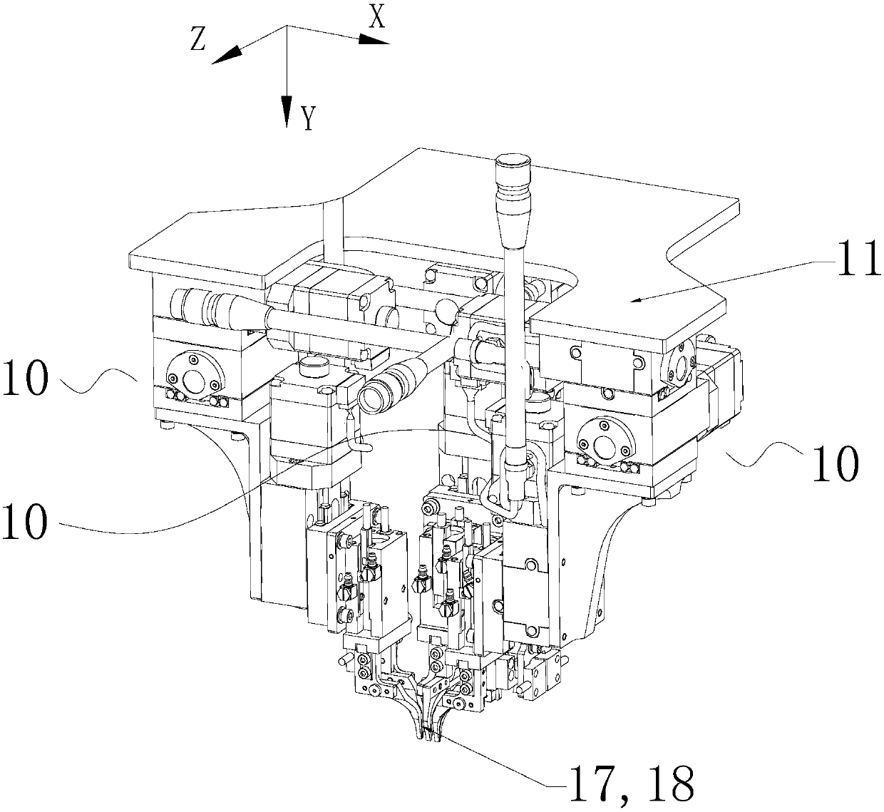
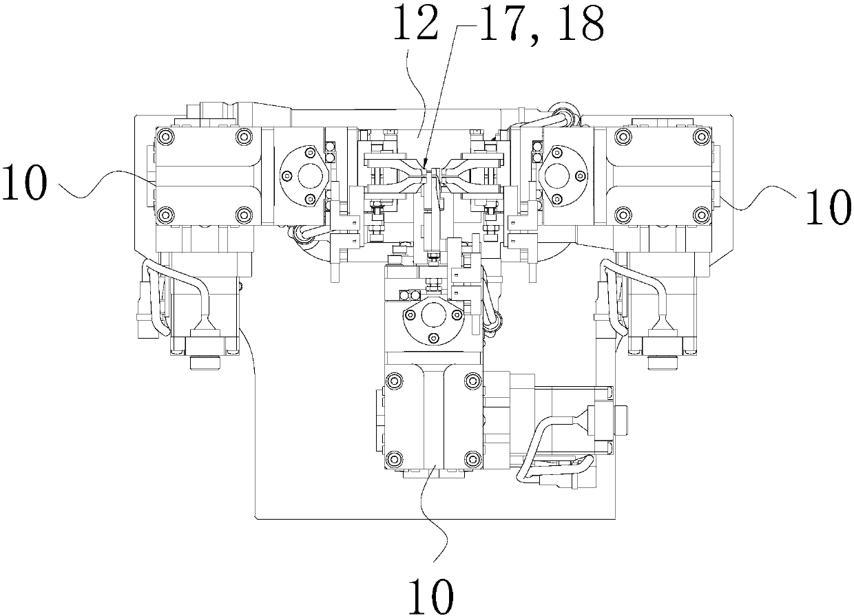
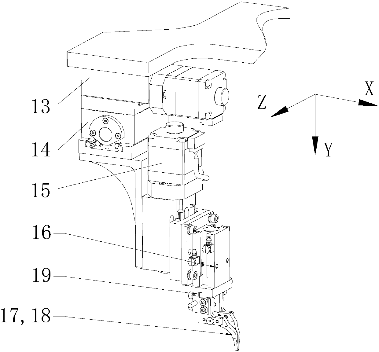
The invention discloses a clamping device. The device comprises a base plate and a plurality of movement execution mechanisms. Each movement execution mechanism comprises a first direction movement device, a second direction movement device and a third direction movement device, wherein the first direction movement device is arranged on the base plate, the second direction movement device is arranged on a work portion of the first direction movement device, and the third direction movement device is arranged on a work portion of the second direction movement device; and a clamping mechanism isarranged on a work portion of the third direction movement mechanism and comprises a clamping portion, and the clamping portion comprises a plurality of clamping jaws and a drive device used for driving the clamping jaws. The multiple movement execution mechanisms perform multithreading parallel operation.

Description

technical field [0001] The present invention relates to the technical field of processing jigs, and more specifically, to a clamping device. Background technique [0002] In the automatic pick-and-place operation of multiple workpieces, it is usually required that the workpieces have a fixed spacing or only a single-dimensional position can be adjusted. When multiple workpieces are required to be picked and placed, and the position spacing is variable, a single-dimensional pick-and-place fixture is generally used for multiple positioning pick-and-place operations. Each step is serially connected sequentially in time sequence. In this way, the progress of the previous steps will affect the subsequent steps, and the processing speed of the workpiece is relatively slow. Contents of the invention [0003] An object of the present invention is to provide a new technical solution for a gripping device. [0004] According to a first aspect of the present invention, a gripping ...

Claims


Application Information

Patent Timeline
IPC IPC(8): B25J9/10B25J15/02B25J19/02B25J13/08
CPCB25J9/10B25J13/08B25J15/0253B25J19/02B25J19/021
Inventor 柴宗明陈太鹏周广福
Owner GEER TECH CO LTD
Why Eureka
Eureka Blog
Learn More