
Jacking pipe cutting protective structure for building remains and construction method thereof

A technology for protecting structures and pipe jacking, applied in building construction, construction, building maintenance, etc., can solve the problems of high site and surrounding environment requirements, power source pollution, slow construction speed, etc., to achieve low site and environmental requirements, engineering The effect of fast progress and fast construction speed

Active Publication Date: 2018-03-27
CHINA CONSTR FIRST BUILDING GRP CORP LTD +2
View PDF6 Cites 9 Cited by
  • Summary
  • Abstract
  • Description
  • Claims
  • Application Information

AI Technical Summary

Benefits of technology

This patented technology improves upon previous methods used during migrations or transit procedures while maintaining their structural integrity. It uses segments divided into smaller sections and placed layers at specific locations along an inclined surface called a shelf level. By adding protective systems around these areas, the movement becomes more secure without damaging valuable assets such as cultural relices from older structures. Additionally, this design allows for quicker installation times due to lower costs compared to traditional ways like drilling holes through concrete slabs. Overall, this new approach enhances safety and efficiency in building constructions.

Problems solved by technology

This patented technical problem addressed by this patents relates to improving the efficiency and safety of traditional methods like pipelay crane installation (PCC). However, these techniques have limitations such as long lead time required for excavations due to limited workspace available at the worksite, expensive equipment needed during operation, loud noises caused by heavy machinery use, environmental concerns associated with burning fossil fuels, etc., which make it difficult to maintain structurally preserved buildings after they were demolished without damaging their cultural heritage.

Method used


Image

  • Jacking pipe cutting protective structure for building remains and construction method thereof
  • Jacking pipe cutting protective structure for building remains and construction method thereof
  • Jacking pipe cutting protective structure for building remains and construction method thereof

Examples


Embodiment Construction

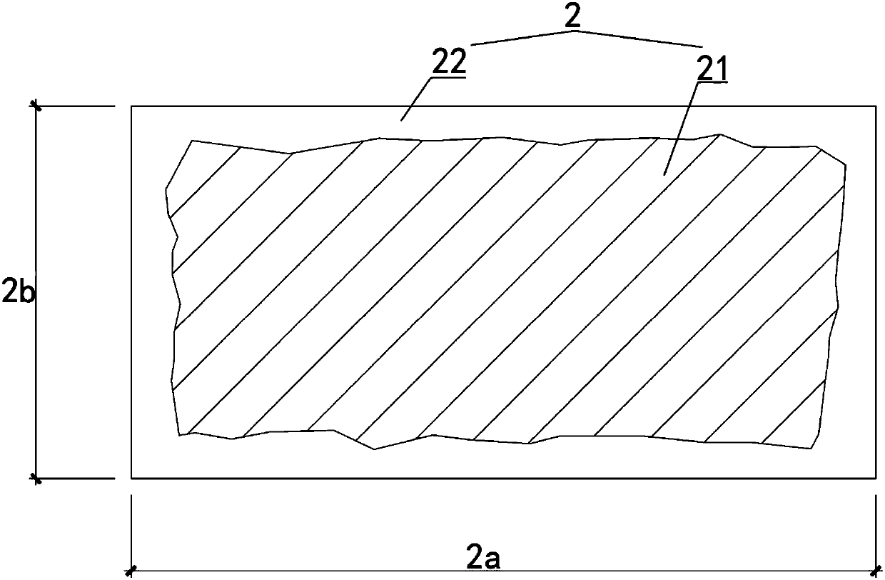
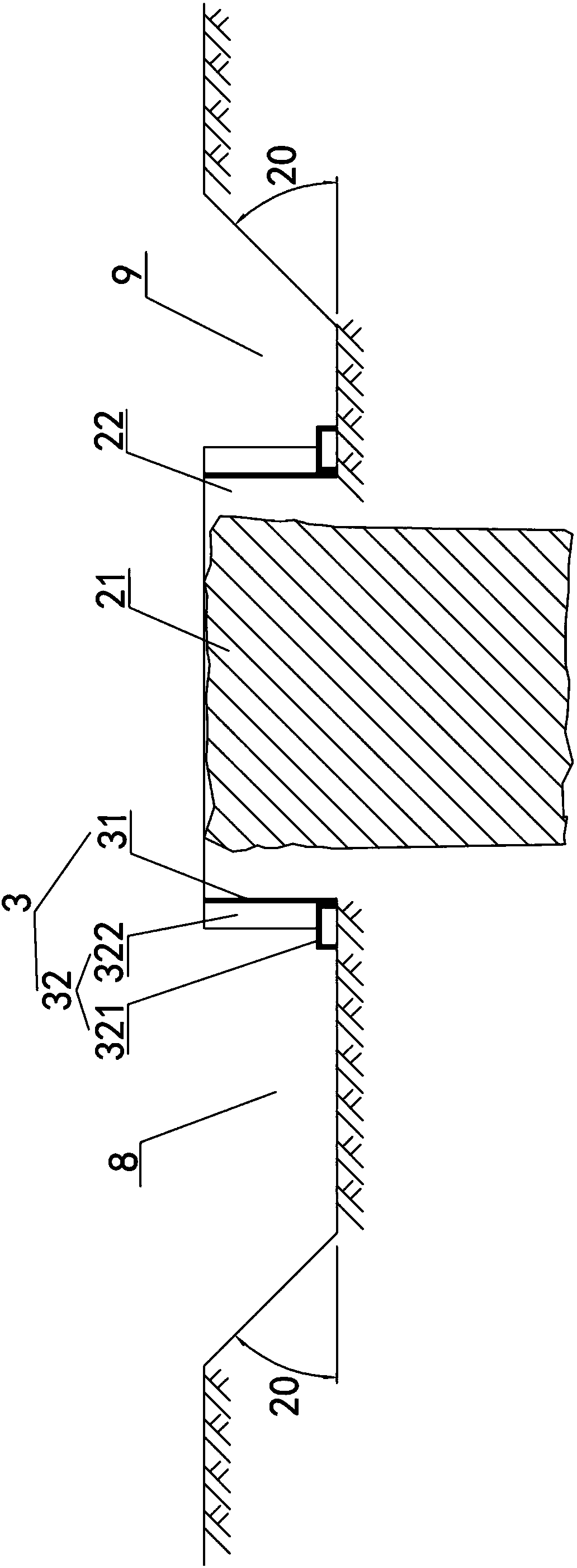
[0057] Examples see Figure 1-Figure 8 , Figure 13-1 , Figure 13-2 , Figure 14-1 and Figure 14-2 As shown, a pipe jacking cutting protective structure for architectural relics, including the earth foundation 1, the migration body 2 on the earth foundation 1, the box-shaped protection system 3 enclosed on the outside of the migration body 2, and the bottom of the supporting migration body 2 and the box The hoisting base 4 at the bottom of the shape protection system 3 . The size of the earthwork foundation 1 is greater than the outer contour size of the box-shaped protective system 3, the migration body 2 includes a protected building body 21 and an earthwork protection shell 22 on the outside of the building body 21, and the migration body 2 is a cuboid, The long side 2a of its cross section is the longitudinal direction, and the short side 2b is the transverse direction. In this embodiment, the height H of the earthwork foundation may be 600 mm.

[0058] see Figur...


PUM


Abstract

The invention discloses a jacking pipe cutting protective structure for building remains and a construction method thereof. The protective structure comprises an earthwork foundation, a migration body, a box-shaped protective system and a hoisting base, and the box-shaped protective system comprises steel plate protective barrels and protective barrel keels; and the hoisting base comprises steel pipe curtains and opening locking steel beams, the opening locking steel beams and the steel pipe curtains are connected to form a whole, and the hoisting base is provided with hanging point structuresfor allowing hoisting ropes to be connected. The construction method of the protective structure comprises the steps of layered excavation of earthwork, pre-reinforcing of the migration body, lateralreinforcing, earthwork foundation construction, surrounding basement treatment, erection of a jack jacking pipe device, jacking trying, steel pipe marching, butting-joint of steel pipes, jacking andpenetrating through of a soil body, connection of the steel pipes and the opening locking steel beams, hoisting point setting, hoisting and the like. According to the jacking pipe cutting protective structure for the building remains and the construction method thereof, site arrangement is easy, the construction progress is quick, interference factors are less, civilized construction is facilitated, various resources can be well utilized, it can be ensured that surrounding existing facilities are intact, and safety of lives and property of residents is ensured.

Description


Claims


Application Information

Patent Timeline
Owner CHINA CONSTR FIRST BUILDING GRP CORP LTD
Learn More