Fluid ejection device with reduced crosstalk

A technology of fluid jetting and fluid jetting, which is applied in the direction of inking device, hose connection device, printing, etc., can solve the problems such as adverse effects on printing quality, achieve reducing fluid crosstalk, stabilizing droplet size and speed, and accurate and precise printing Effect

Active Publication Date: 2019-09-06
FUJIFILM DIMATIX
View PDF7 Cites 0 Cited by
  • Summary
  • Abstract
  • Description
  • Claims
  • Application Information

AI Technical Summary

Problems solved by technology

This fluid crosstalk can adversely affect print quality

Method used


Image

  • Fluid ejection device with reduced crosstalk
  • Fluid ejection device with reduced crosstalk
  • Fluid ejection device with reduced crosstalk

Examples


Embodiment Construction

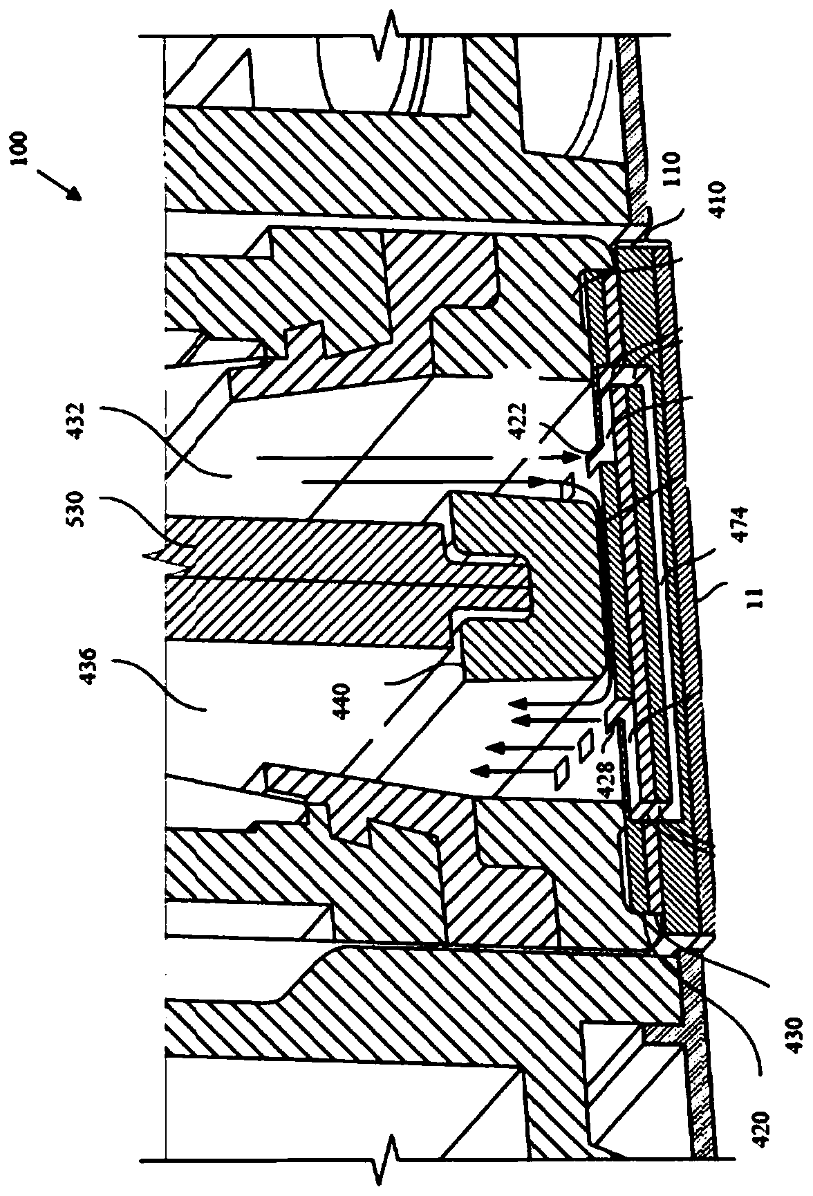
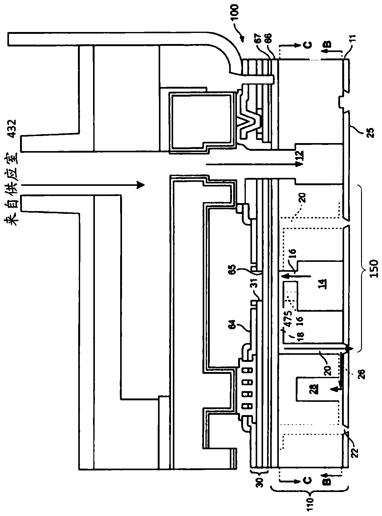
[0036] refer to figure 1 , the printhead 100 may be used to eject fluid droplets such as inks, biological fluids, polymers, liquids used to form electronic components, or other types of fluids onto a surface. The printhead 100 includes a housing 410 having an interior volume that is divided into a fluid supply chamber 432 and a fluid return chamber 436 , for example by an upper partition 530 and a lower partition 440 .

[0037] The bottoms of the fluid supply chamber 432 and the fluid return chamber 436 are defined by the top surface of the insert assembly. The insert assembly may be attached to the lower printhead housing 410, for example, by adhesive, friction, or other attachment mechanisms. The insert assembly may include an upper insert 420 and a lower insert 430 between the upper insert 420 and the base plate 110 .

[0038] Upper insert 420 includes a fluid supply inlet 422 and a fluid return outlet 428 . For example, fluid supply inlet 422 and fluid return outlet 428...


PUM


Abstract

A fluid ejection device includes a plurality of fluid ejectors. Each fluid injector includes a pumping chamber and an actuator configured to cause fluid to be ejected from the pumping chamber. The fluid ejection device includes a supply channel fluidly connected to each pumping chamber; and at least one flexible structure formed in a surface of the supply channel. The at least one flexible structure has a lower compliance than the surface of the feed channel.

Description

technical field [0001] The present disclosure generally relates to fluid ejection devices. Background technique [0002] In some fluid ejection devices, fluid droplets are ejected onto media from one or more nozzles. The nozzle is fluidly connected to a fluid path that includes a fluid pumping chamber. The fluid pumping chamber may be actuated by an actuator that causes ejection of fluid droplets. The media is movable relative to the fluid ejection device. The time at which a fluid droplet is ejected from a particular nozzle is timed with the movement of the media to place the fluid droplet at a desired location on the media. Ejecting fluid droplets of uniform size and velocity and in the same direction enables uniform deposition of the fluid droplets onto the media. Contents of the invention [0003] When the fluid injector's actuator is activated, pressure fluctuations can propagate from the pumping chamber to the connected inlet and outlet supply channels. This pre...

Claims


Application Information

Patent Timeline
Patent Type & Authority Patents(China)
IPC IPC(8): B41J2/14B41J2/175B41J2/20B41J2/22F16L33/16
CPCB41J2/14B41J2/14233B41J2/161B41J2/1623B41J2/1628B41J2/1629B41J2/1631B41J2/1632B41J2002/14459B41J2202/12B41J2/1433B41J2/162B41J2/164B41J2/055B41J2/04525
Inventor C.门泽尔K.V·冯埃森S.H.巴尔斯M.G.奥图森D.伊迈
Owner FUJIFILM DIMATIX
Why Eureka
Try Eureka