Diaphragm air pump

a technology of diaphragm and air pump, which is applied in the direction of piston pumps, positive displacement liquid engines, cooling/ventilation/heating modifications, etc., can solve the problems of limiting the miniaturization of electronic appliances or devices, affecting the miniaturization effect of electronic appliances, and affecting the cooling effect of microelectronic parts

Inactive Publication Date: 2005-04-28
SAMSUNG ELECTRONICS CO LTD +1
View PDF5 Cites 92 Cited by
  • Summary
  • Abstract
  • Description
  • Claims
  • Application Information

AI Technical Summary

Benefits of technology

[0013] To solve parts of the above-mentioned problems occurring in the related art, accordingly, the present invention is to provide a d...

Problems solved by technology

As integration of transistors increases in compact electronic appliances or devices, microelectronic parts may be caused to malfunction or damaged due to heat produced within the electronic appliances or devices.
Therefore, the problem of cooling microelectronic parts becomes an important issue for those electronic appliances using such microelectronic parts.
In addition, as electronic appliances such as computers become more compact, coolers for cooling chips therein should occupy a smaller volume of space while consuming less power.
However, the cooler or air supply apparatus for a fuel cell with the above-mentioned constructions may generate noise...

Method used


Image

  • Diaphragm air pump
  • Diaphragm air pump
  • Diaphragm air pump

Examples


Embodiment Construction

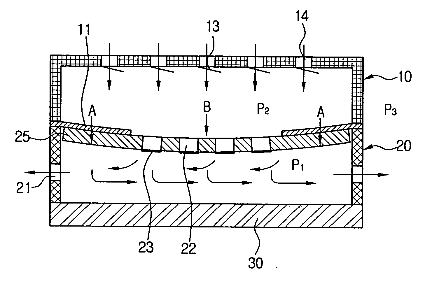
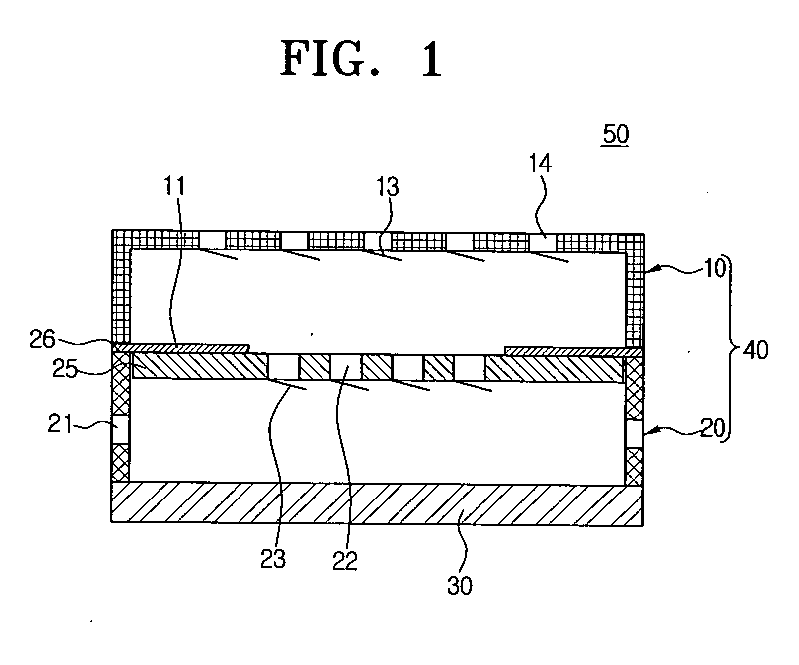
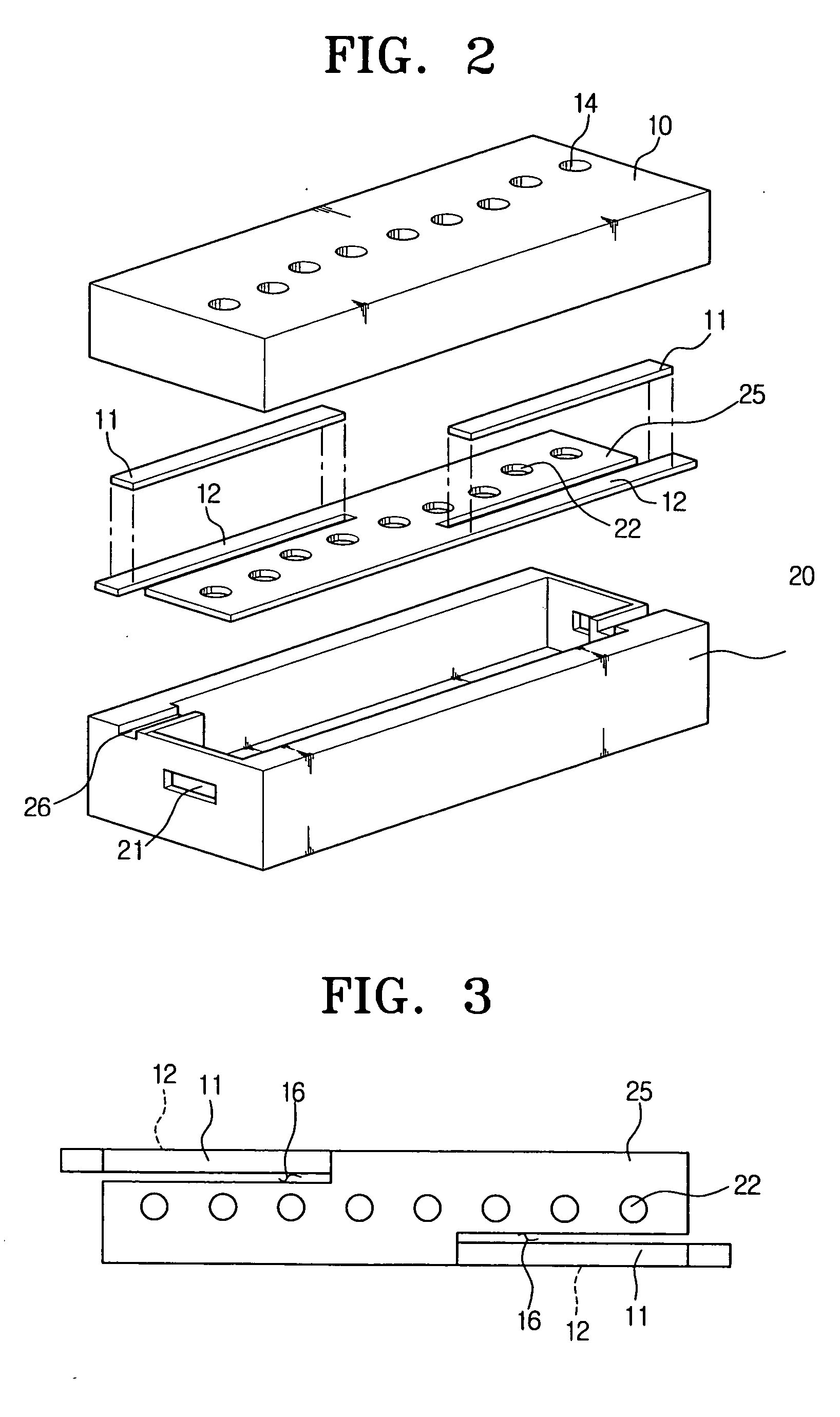
[0029] Diaphragm air pumps according to the embodiments of the present invention will be described in detail with reference to the accompanying figures. FIG. 1 is a cross-sectional view of a diaphragm air pump according to the first embodiment of the present invention, FIG. 2 is a perspective view of the diaphragm air pump shown in FIG. 1, FIG. 3 is a top plan view of the diaphragm with the piezoelectric beams shown in FIGS. 1 and 2.

[0030] Referring to these drawings, the diaphragm air pump 50 generally comprises a pump chamber 40, a diaphragm 25 provided in the pump chamber 40, and one or more piezoelectric beams 11.

[0031] The pump chamber 40 provides an appearance of the diaphragm air pump 50, and external fluid, such as air, flows into the pump chamber 40 and flows out of it. In addition, the pump chamber 40 comprises an upper case 10 and a lower case 20.

[0032] In the top of the upper case 10, one or more inlet openings 14 are formed, through which fluid flows into the upper c...


PUM


Abstract

A diaphragm air pump comprises a pump chamber, a diaphragm and one or more piezoelectric beams or bimorphs. Fluid flows into the pump chamber and then flows out of it, the diaphragm is provided within the pump chamber, and one or more central openings are formed in the diaphragm. One or more central check valves are provided in the central openings. The diaphragm is just bonded with piezoelectric beams, not fixed to the lower housing of the pump chamber in order to get large displacement. With the provided diaphragm air pump, it is possible to actively adjust the air quantity according to the requirement for fuel cell or a part-to-be-cooled, and it is also possible to reduce noise and power consumption compared with a conventional fan type cooler or air pumps.

Description

CROSS-REFERENCE TO RELATED APPLICATIONS [0001] This application claims the benefit of Chinese Patent Application No. 03157069.0 filed on Sep. 12, 2003 in the State Intellectual Property Office of the People's Republic of China and Korean Patent Application No. 2004-51674 filed on Jul. 2, 2004 in the Korean Intellectual Property Office, the disclosures of which are incorporated herein by reference in their entirety. BACKGROUND OF THE INVENTION [0002] 1. Field of the Invention [0003] The present invention relates to a diaphragm air pump, and more particularly, to a compact diaphragm air pump driven by a bimorph. [0004] 2. Description of the Related Art [0005] In general, a compact air supply apparatus such as an air pump is used to supply a certain quantity of air to a compact electronic appliance or device. [0006] As integration of transistors increases in compact electronic appliances or devices, microelectronic parts may be caused to malfunction or damaged due to heat produced with...

Claims


Application Information

Patent Timeline
IPC IPC(8): F04B43/04F04B45/04F04B45/047
CPCF04B43/046F04B45/047F04B45/045
Inventor CHO, HYE-JUNGLUO, XIAOBINGZHOU, ZHAOYINGYANG, XINGYE, XIONGYING
Owner SAMSUNG ELECTRONICS CO LTD
Why Eureka
Try Eureka