Downhole fluid pumping apparatus and method

Active Publication Date: 2006-10-24
SCHLUMBERGER TECH CORP
View PDF21 Cites 94 Cited by
  • Summary
  • Abstract
  • Description
  • Claims
  • Application Information

AI Technical Summary

Benefits of technology

[0013]Other aspects and advantages of the invention will be apparent from the following description and the appended claims.

Problems solved by technology

Because of the great expense and rig time required to “trip” the drill pipe, wireline tools are generally used only when the information is absolutely needed or when the drill string is tripped for another reason, such as changing the drill bit.

Method used


Image

  • Downhole fluid pumping apparatus and method
  • Downhole fluid pumping apparatus and method
  • Downhole fluid pumping apparatus and method

Examples


Embodiment Construction

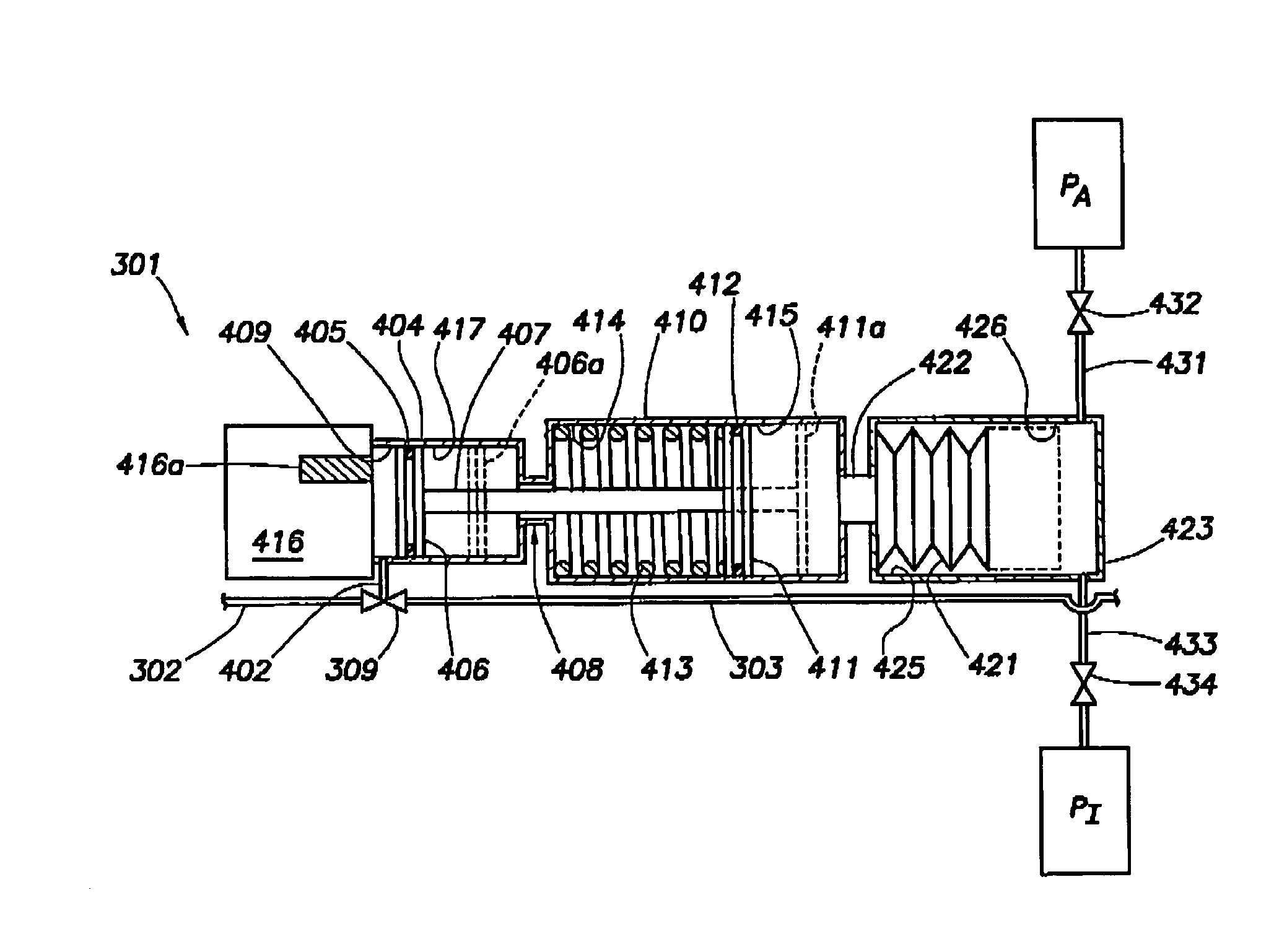
[0024]In one or more embodiments, the invention relates to a fluid pump that may be used in a downhole drilling environment. In some embodiments, the invention relates to a method for using a fluid pump. In one or more embodiments, the invention relates to a formation evaluation while drilling tool that includes a fluid pump. In some other embodiments, the invention relates to a method of formation evaluation while drilling. The invention will now be described with reference to the attached drawings.

[0025]The phrase “formation evaluation while drilling” refers to various sampling and testing operations that may be performed during the drilling process, such as sample collection, fluid pump out, pretests, pressure tests, fluid analysis, and resistivity tests, among others. It is noted that “formation evaluation while drilling” does not necessarily mean that the measurements are made while the drill bit is actually cutting through the formation. For example, sample collection and pump...


PUM


Abstract

A downhole fluid pump including a pump chamber, and a piston disposed in the pump chamber so that the piston will move in one selected from a charge stroke and a discharge stroke when the piston is exposed to a differential pressure. The downhole fluid pump may form part of a formation evaluation while drilling tool.

Description

BACKGROUND OF INVENTION[0001]Wells are generally drilled into the ground to recover natural deposits of oil and gas, as well as other desirable materials, that are trapped in geological formations in the Earth's crust. A well is typically drilled using a drill bit attached to the lower end of a “drill string.” Drilling fluid, or “mud,” is typically pumped down through the drill string to the drill bit. The drilling fluid lubricates and cools the drill bit, and it carries drill cuttings back to the surface in the annulus between the drill string and the borehole wall.[0002]It is often desirable to have information about the subsurface formations that are penetrated by a well. For example, one aspect of standard formation evaluation relates to the measurements of the formation pressure and formation permeability. These measurements are essential to predicting the production capacity and production lifetime of a subsurface formation.[0003]One technique for measuring formation propertie...

Claims


Application Information

Patent Timeline
Patent Type & Authority Patents(United States)
IPC IPC(8): E21B49/10E21B34/10E21B49/08
CPCE21B49/081E21B34/101E21B49/10
Inventor CIGLENEC, REINHARTKIBSGAARD, PAALVILLAREAL, STEVEN G.
Owner SCHLUMBERGER TECH CORP
Why Eureka
Try Eureka