Vacuum pump with shock absorption and controlled rotation for prosthetic devices

a technology of vacuum pump and prosthesis, which is applied in the direction of prosthesis, positive displacement liquid engine, liquid fuel engine, etc., can solve the problems of nerve bundle pressure or restriction problems, large stump shear force, and special consideration

Active Publication Date: 2005-10-27
OTTO BOCK HEALTHCARE IP GMBH & CO KG
View PDF42 Cites 94 Cited by
  • Summary
  • Abstract
  • Description
  • Claims
  • Application Information

AI Technical Summary

Benefits of technology

[0021] In an alternate embodiment, the present invention provides vacuum pump for use in an artificial limb including a prosthetic foot having an integral pylon. The vacuum pump includes a housing couplable to a prosthetic structure, the housing including a first chamber; a shaft configured to be received by and to reciprocate within the first chamber, with the housing and shaft together forming a pump chamber, and an intake port and an exhaust port fluidly couple

Problems solved by technology

These types of sockets caused a lot of shear force on the stump 52, as well as had pressure or restriction problems on the nerve bundles and vascular flow of fluid by way of the circumferential pressure effect of the socket on the limb.
However, problematic tissue configurations, such as bony prominences, required special consideration, such as the addition of soft or pliable materials to be put into the socket.
Some of the problems with these positive pressure systems are that they use a very specific pressure at specific locations resulting in the creation of atrophy and loss of tissue dramatically over

Method used


Image

  • Vacuum pump with shock absorption and controlled rotation for prosthetic devices
  • Vacuum pump with shock absorption and controlled rotation for prosthetic devices
  • Vacuum pump with shock absorption and controlled rotation for prosthetic devices

Examples


first embodiment

[0064] As shown in FIGS. 4-18, a vacuum pump 200, in accordance with the present invention, is shown including a shaft 210 and a housing 220. At a first end 201 of the pump 200, the shaft 210 includes an integral coupler 212 formed as a receiver to receive a prosthetic structure, such as prosthetic pyramid, pylon 104 or other suitable structure. A plurality of fasteners, such as four set screws 213, are provided to secure or fasten the prosthetic structure to the shaft 210 at the coupler 212. Providing an integral coupler 212 can be more cost effective and robust than other models using a separate coupler, although a separate coupler would work. At an opposite end 202 of the pump 200, the housing 220 is configured to receive a suitable connector, such as a pyramid connector commonly used in the prosthetic industry or any other suitable connector. The housing 220 is provided with a four-hole bolt pattern 205 common to prosthetic components, allowing the attachment of variety of diffe...

second embodiment

[0078] As shown in FIGS. 19-29, a vacuum pump 300 in accordance with the present invention includes a shaft 310 and a housing 320. The housing 320 includes a base 330 and a cap 340. At a first end 301 of the pump 300, the shaft 310 includes an integral coupler 312 formed as a tube clamp. In one embodiment, the tube clamp is sized for 30 mm tubes, a common prosthetic industry component. In addition to the tube clamp of coupler 312 and the receiver of coupler 212, other types of attachment configurations, now known or later utilized in the prosthetic industry, formed integrally with a shaft or added to the shaft may also be provided, and are within the scope of the present invention.

[0079] At an opposite end 302 of the pump 300, the housing 320 at cap 340 includes a integrally formed prosthetic pyramid connector 305. Inclusion of the connector 305 integral with the pump housing 320 saves height and weight. In addition, it may provide a cost savings because a practitioner selling, dist...

fourth embodiment

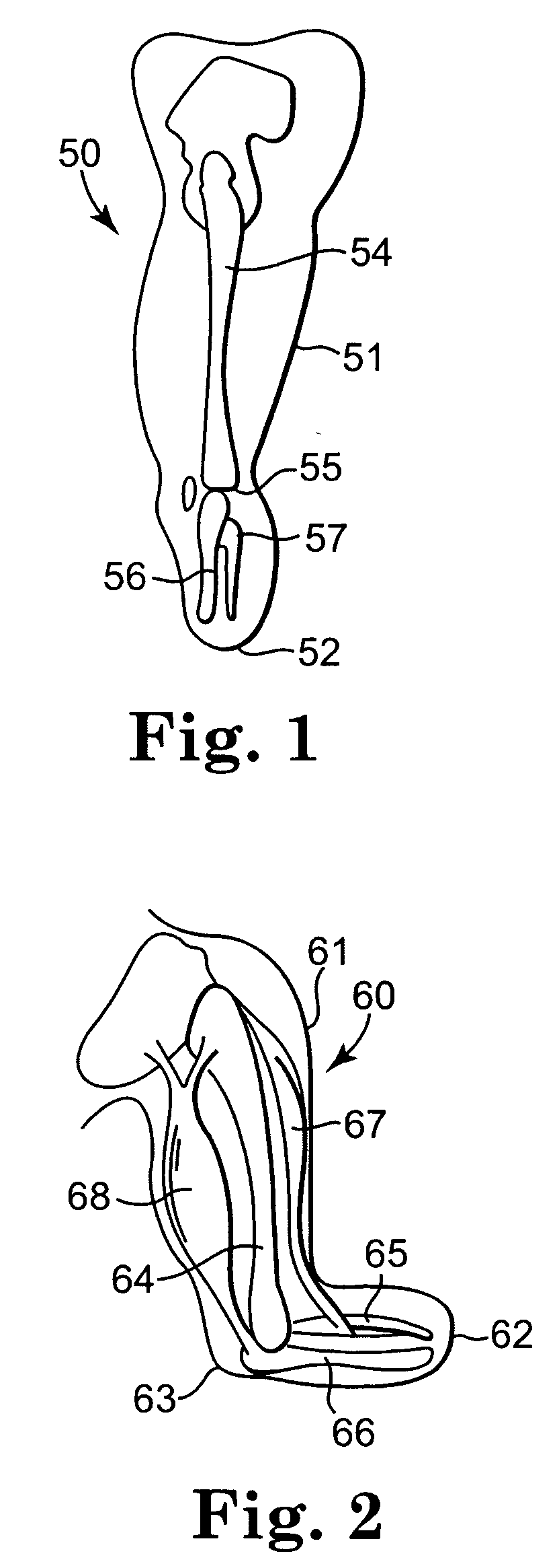
[0088] Referring now to FIGS. 33-35, a vacuum pump in accordance with the present invention is shown adapted for attachment to an integral pylon-style prosthetic foot. In FIG. 33, a prosthetic foot 550 includes a generally, vertically oriented integral pylon 552 having an external profile 554. The profile 554 is shown as being generally oblong, having curved ends 555 and elongated straight sides 556. However, other profiles are also possible, including profiles that are oval, elliptical, rectangular or other suitable shapes. By integral pylon, it is meant that a pylon-type structure is formed in conjunction with a portion of the foot and / or ankle structure.

[0089] The vacuum pump 500 of this embodiment is shown to be similar to pump 300 of the second embodiment and includes the same or similar internal and external components as those described above for any of the embodiments, such that the components may be mixed and matched as needed. However, in this embodiment, the shaft 510 inc...


PUM


Abstract

A vacuum pump having shock absorption and controlled rotation for use in an artificial limb. The pump includes a housing having a first chamber, and a shaft configured to be received by and to reciprocate within the first chamber, the housing and shaft forming a pump chamber. A piston may be coupled to the shaft and positioned within the pump chamber, and intake and exhaust ports are fluidly coupled to the pump chamber. Rotational structure is mounted with respect to the pump to provide controlled rotation of the shaft relative to the housing, and shock absorption structure is included within the pump to provide shock absorption for the shaft. Both a pneumatic spring and a mechanical spring element may be provided for the shock absorption structure. An optional adapter couples the shaft to the pylon of an integral pylon prosthetic foot.

Description

[0001] The present application claims the benefit of co-pending provisional patent application Ser. No. 60 / 564,423, entitled VACUUM PUMP WITH SHOCK ABSORPTION AND CONTROLLED ROTATION FOR PROSTHETIC DEVICES, filed on Apr. 22, 2004, and herein incorporated by reference in its entirety.TECHNICAL FIELD [0002] The present invention is related to vacuum pumps usable in prosthetic devices, such as artificial legs or arms. In particular, it is related to vacuum pumps including shock absorption and torsion. BACKGROUND [0003] An amputee is a person who has lost part of an extremity or limb such as a leg or arm, the remainder of which commonly may be termed as a residual limb. Residual limbs come in various sizes and shapes with respect to the stump. That is, most new amputations are either slightly bulbous or cylindrical in shape while older amputations that may have had a lot of atrophy are generally more conical in shape. Residual limbs may further be characterized by their various individu...

Claims


Application Information

Patent Timeline
IPC IPC(8): A61F2/50A61F2/60A61F2/66A61F2/74A61F2/76A61F2/78A61F2/80
CPCA61F2/60A61F2002/805A61F2/76A61F2/78A61F2/80A61F2002/5003A61F2002/5007A61F2002/503A61F2002/5072A61F2002/5083A61F2002/5084A61F2002/607A61F2002/6614A61F2002/742A61F2002/747A61F2002/748A61F2/601A61F2/742A61F2/74A61F2/748
Inventor RUSH, DOUGLAS E.WILLIAMS, NATHAN A.FINLINSON, ROBERT EDWARDMOSLER, LUDERHILLMANN, MARTINSKIERA, RICHARD
Owner OTTO BOCK HEALTHCARE IP GMBH & CO KG
Why Eureka
Try Eureka