
Hall-effect thruster usable at high altitude

A technology of Hall effect and propulsion, which is applied in the direction of aerospace vehicles, aircraft, thrust reversers, etc., and can solve the problem that the propeller cannot operate.

Active Publication Date: 2018-03-27
SAFRAN AIRCRAFT ENGINES SAS
View PDF6 Cites 2 Cited by
  • Summary
  • Abstract
  • Description
  • Claims
  • Application Information

AI Technical Summary

Problems solved by technology

[0005] However, these thrusters cannot operate at altitudes of around 100 km, given the thin atmosphere at this altitude

Method used


Image

  • Hall-effect thruster usable at high altitude
  • Hall-effect thruster usable at high altitude
  • Hall-effect thruster usable at high altitude

Examples


Embodiment Construction

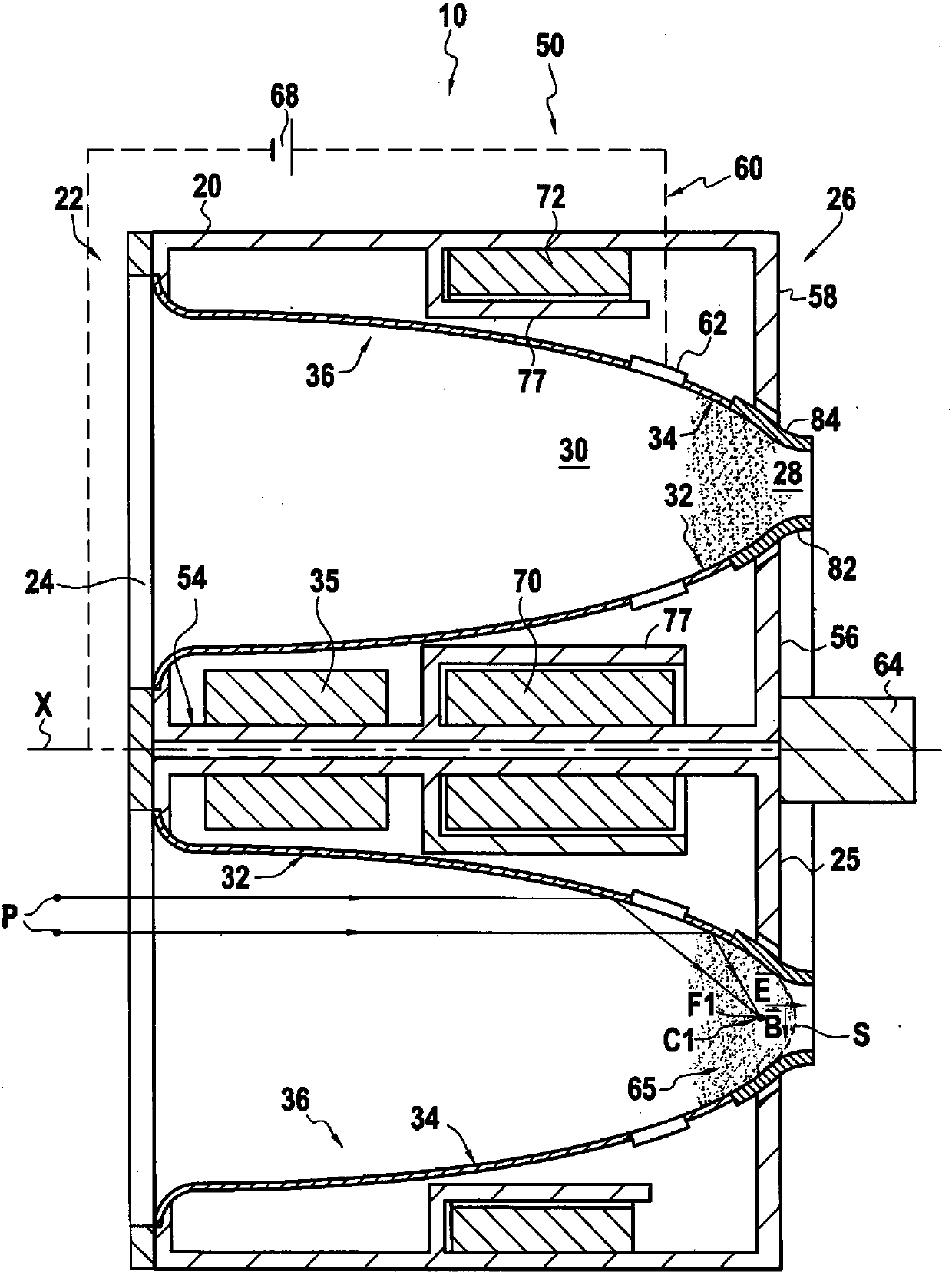
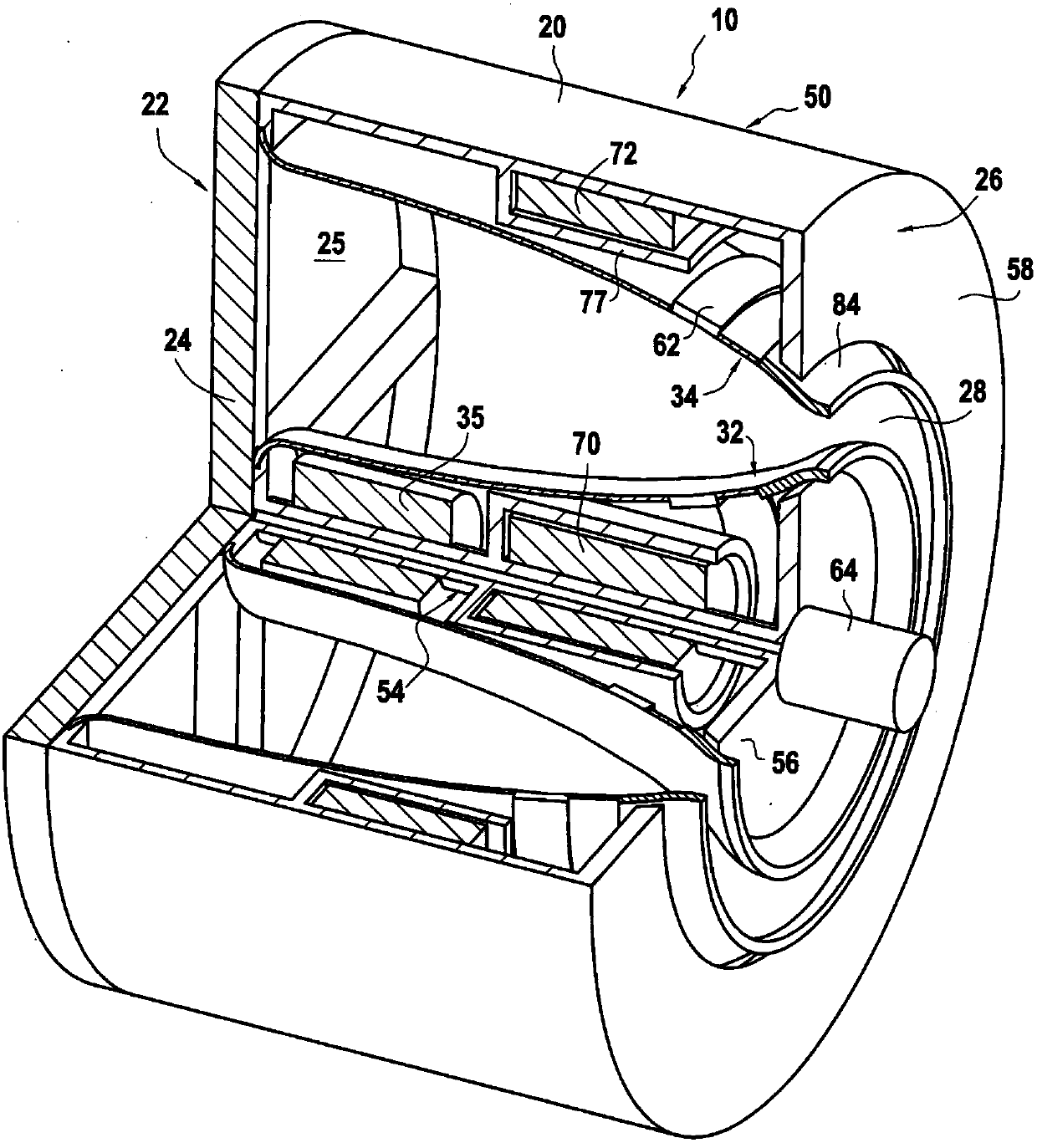
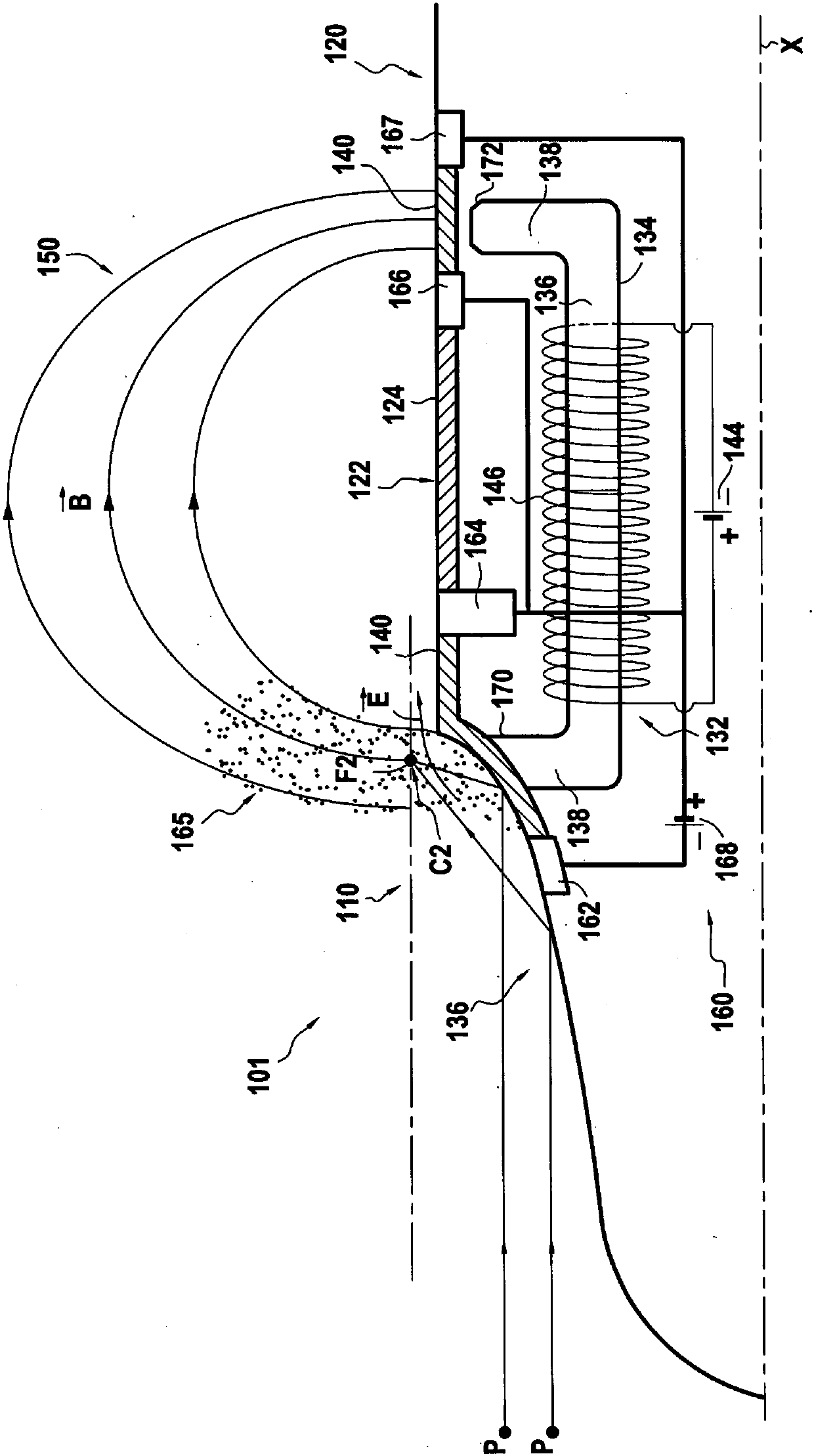
[0064] Two embodiments of the invention, corresponding respectively to its first and second aspects, will now be illustrated by means of two satellites 1 and 101 respectively comprising a thruster 10 and a thruster 110 according to the invention.

[0065] These satellites 1 and 101 are satellites intended for maneuvering in the Earth's atmosphere while maintaining altitudes between 100 and 300 km.

[0066] Advantageously, this altitude is relatively low, which allows certain devices (communication devices, cameras, etc.) to be relatively small in size and thus of low mass. Instead, at this altitude, the Earth's atmosphere provides a slight but non-zero drag on the passage of satellites. It is therefore necessary to compensate for induced drag.

[0067] The job of each of these satellites' Hall-effect thrusters is to provide thrust to the satellite to keep it operating at the desired altitude.

[0068] It also allows track changes or corrections to be provided.

[0069] Adva...


PUM


Abstract

The invention relates to a Hall-effect thruster (10), configured to be arranged inside or outside a spacecraft. The thruster has a concentrator (36) for collecting particles (P). The shape of this concentrator is defined by a continuous contour (C1) that wraps around the thrust axis and is such that along a major portion of the contour, each cross-section of the concentrator perpendicular to the contour is parabola-shaped and has a focus (F1) belonging to the contour (C1). The magnetic circuit (50) is further arranged to generate the magnetic field (B) adjacent to the contour (C1).

Description

technical field [0001] The invention relates to the field of Hall effect thrusters using atmospheric gas as propellant. Background technique [0002] Document US 2003 / 046921 describes a Hall effect thruster with atmospheric gas as propellant. Such thrusters use particles from the remaining atmosphere, mobilized in the thruster. [0003] Hall-effect thrusters, which use atmospheric gases as propellants, are primarily used to propel observation satellites, and these thrusters are particularly useful in low orbits. [0004] At this altitude, the remaining atmosphere slows down the satellites, limiting their lifetime. Advantageously, Hall effect thrusters with atmospheric gas as propellant allow to compensate for this drag, thereby increasing the lifetime of the satellite. [0005] However, these thrusters cannot operate at altitudes of around 100 kilometers, given the thin atmosphere at this altitude. Therefore, they are not usable above this altitude, for example to allow ...

Claims


Application Information

Patent Timeline
Patent Type & Authority Applications(China)
IPC IPC(8): F03H1/00
CPCF03H1/0012F03H1/0075B64G1/405
Inventor 弗雷德里克·拉斐尔·琼·马尚迪斯斯蒂芬·祖尔巴赫
Owner SAFRAN AIRCRAFT ENGINES SAS
Learn More