
Displayer supporting device

A support device and display technology, which is applied in the direction of supporting machines, machines/brackets, mechanical equipment, etc., can solve the problems of not being able to adapt to the support of the display, the inconvenient movement of the display base, etc., and achieve the effect of improving wear resistance and strength

Inactive Publication Date: 2018-03-30
HEFEI HUIKE JINYANG TECH
View PDF6 Cites 1 Cited by
  • Summary
  • Abstract
  • Description
  • Claims
  • Application Information

AI Technical Summary

Problems solved by technology

[0003] The purpose of the present invention is to provide a display supporting device, which solves the problem that the existing display base is not easy to move and cannot adapt to the support of displays of different sizes

Method used


Image

  • Displayer supporting device
  • Displayer supporting device

Examples


Embodiment 1

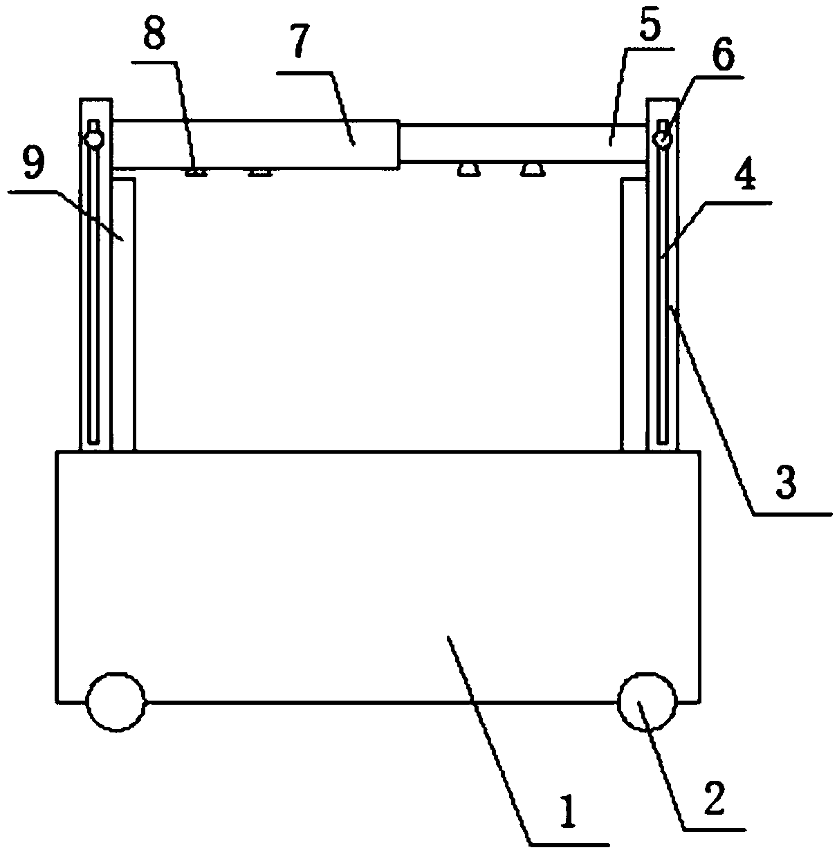
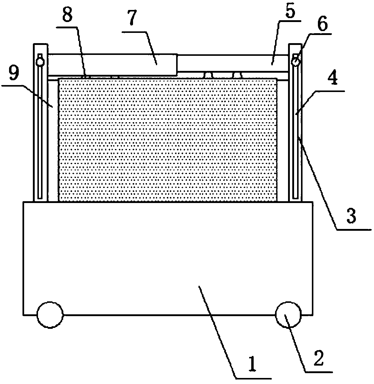
[0029] see Figure 1 to Figure 2 , the present invention provides a display support device, including: base 1, universal wheel 2, side support frame 3, first top support frame 5, adjustment nut 6, second top support frame 7, rubber pad 8 and side rubber pad 9; the universal wheel 2 is arranged on the bottom of the base 1, and the number of the side support frame 3 is two, which are respectively arranged on both sides above the base 1; the side support frame 3 A vertically downward hollow chute 4 is arranged on the top, and the first top support frame 5 and the second top support frame 7 are slidably connected in the hollow chute 4 through the adjustment nut 6 respectively; The second top support frame 7 is sleeved on the outside of the first top support frame 5, and the first top support frame 5 and the second top support frame 7 are telescopic; the rubber pad 8 is arranged on the first top support frame. The bottom surface of the top support frame 5 and the second top suppor...

Embodiment 2

[0032] A manufacturing process of a support height adjustment mechanism of a display support device, the steps are as follows:

[0033] 1), structure and separate processing

[0034] The support height adjustment mechanism includes a base, a side support frame, a top support frame, and an adjustment nut; the number of side support frames is two, which are respectively arranged on both sides above the base; the side support frame is provided with vertically downward Hollow chute, both ends of the top support frame are slidably connected in the hollow chute through adjusting nuts;

[0035] The base is made of welded stainless steel plate, the material of the side support frame and the top support frame is Q235 steel, and the hollow chute is formed by milling; the adjustment nut is prepared according to the existing technology;

[0036] 2), pre-processing

[0037] Soak the side support frame in the bath for 1 hour, then rinse;

[0038] The bath composition is: 7 parts of polyg...


PUM


Abstract

The invention relates to the technical field of display, in particular to a displayer supporting device. The displayer supporting device comprises a foundation support, universal wheels, side supporting frames, a first top supporting frame, adjustment nuts, a second top supporting frame, rubber pads and side rubber pads. The universal wheels are arranged at the bottom of the foundation support, and the two side supporting frames are arranged on the two sides of the upper portion of the foundation support correspondingly. The side supporting frames are provided with vertically-downward hollowed-out sliding chutes, and the first top supporting frame and the second top supporting frame are slidably connected into the hollowed-out sliding chutes through the adjustment nuts correspondingly. Thesecond top supporting frame is arranged outside the first top supporting frame in a sleeved manner, and the first top supporting frame and the second top supporting frame are stretchable. The rubberpads are arranged on the bottom faces of the first top supporting frame and the second top supporting frame. The side rubber pads are arranged on the inner walls of the side supporting frames. A displayer can be fixed steadily and moved anytime and anywhere; and in addition, the displayer supporting device is adjustable in size and capable of supporting displayers in difference sizes.

Description

technical field [0001] The invention relates to the field of display technology, in particular to a display support device. Background technique [0002] Liquid crystal display is a flat and ultra-thin display device, which is composed of a certain number of color or black and white pixels, placed in front of the light source or reflective surface. Liquid crystal displays consume very little power, making them favored by engineers for electronic devices that run on batteries. Its main principle is to stimulate liquid crystal molecules with current to generate points, lines, and surfaces to form a picture with the back lamp tube. Existing monitors usually have a base for easy placement, but the base is inconvenient to move and cannot be supported by monitors of different sizes. Contents of the invention [0003] The object of the present invention is to provide a display supporting device, which solves the problem that the existing display base is inconvenient to move and...

Claims


Application Information

Patent Timeline
Patent Type & Authority Applications(China)
IPC IPC(8): F16M11/04F16M11/22
CPCF16M11/04F16M11/22
Inventor 白航空
Owner HEFEI HUIKE JINYANG TECH
Learn More