Gas explosion characteristic structure effect testing system
A gas explosion and testing system technology, applied in the direction of material explosion, can solve the problems that the research results are not widely applicable, the structural effects of combustible gases cannot be systematically studied, and the actual working conditions cannot be solved, so as to ensure air tightness and experimental Fully equipped effect
- Summary
- Abstract
- Description
- Claims
- Application Information
AI Technical Summary
Problems solved by technology
Method used
Image

Examples
Embodiment 1
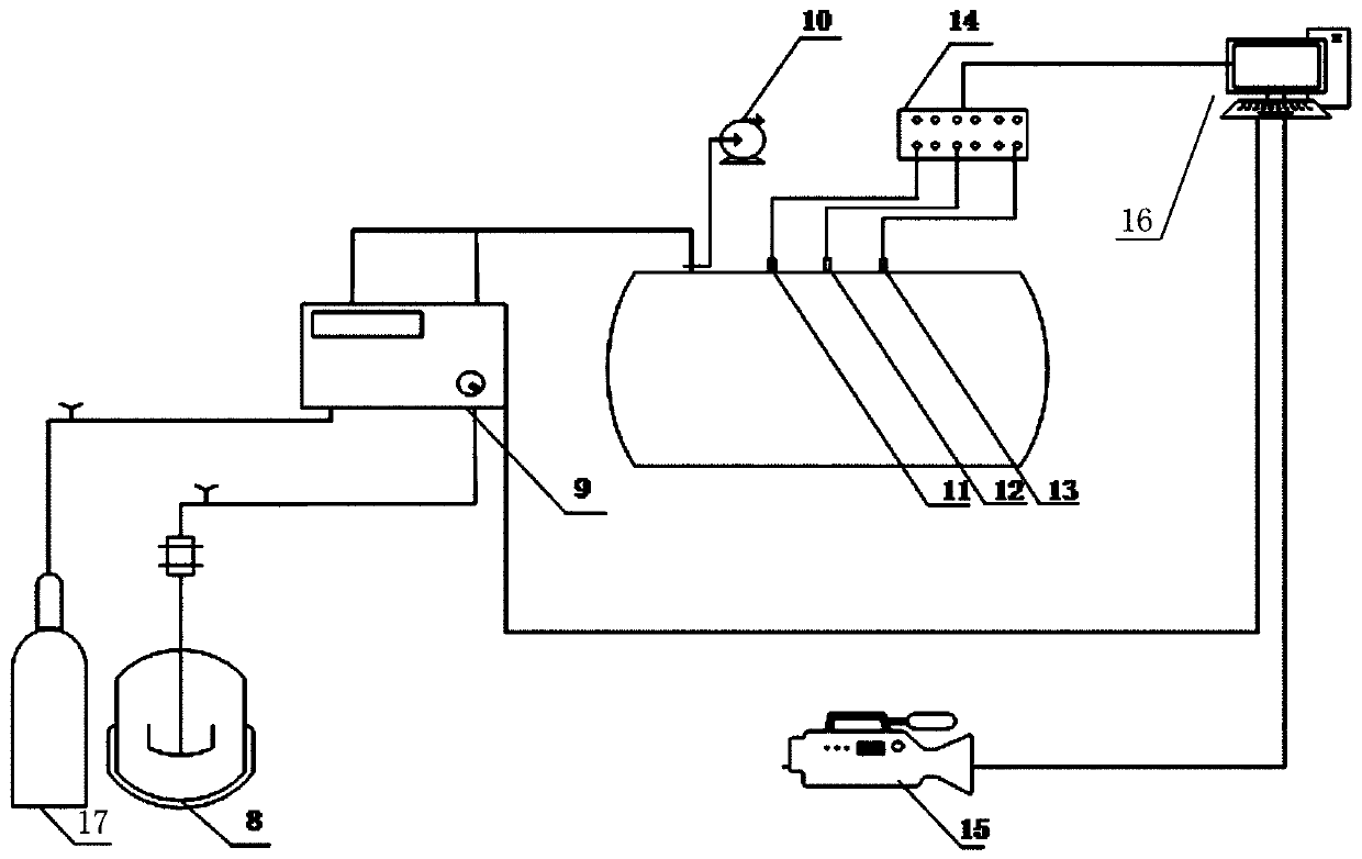
[0048] as attached Figure 1~2 As shown, a test system for the structural effect of gas explosion characteristics is composed of a gas distribution system, an ignition device, an explosion device, a data acquisition and analysis device, and a high-speed digital camera.
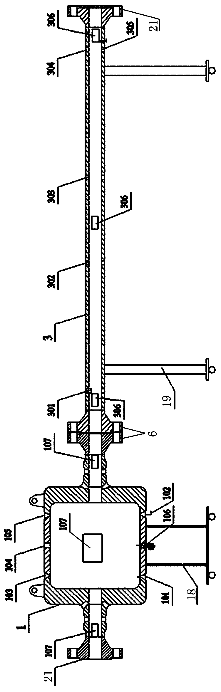
[0049] The explosive device comprises a cylindrical container 1 and a linear pipeline 3, two horizontal conduits with flanges 21 are arranged at the two ends of the cylindrical container 1, and flanges 21 are provided at the two ends of the linear pipeline 3. The cylindrical container 1 is connected with the straight pipe 3 through a flange 21 through one section of the horizontal conduit, and the flange 21 of the other section of the horizontal conduit of the cylindrical container 1 is blocked with a blind plate 20, and the other end of the straight pipe 3 is also The flange 21 is blocked with a blind plate 20 .
[0050] The cylindrical container 1 is respectively provided with a first ignition gun installat...
Embodiment 2
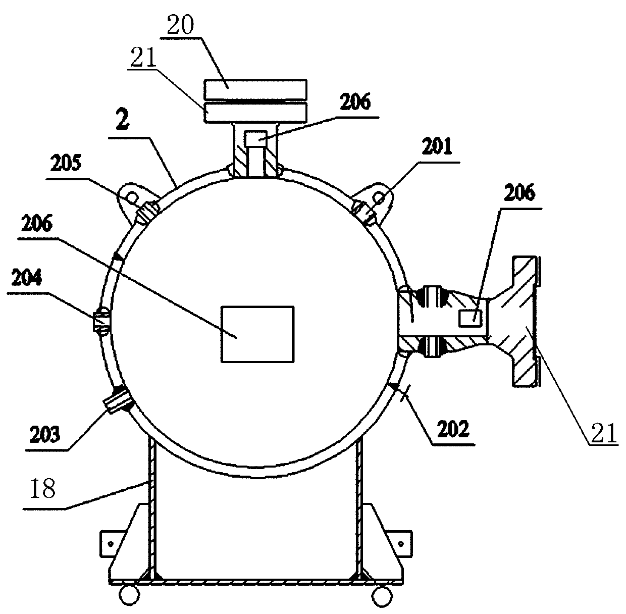
[0059] The cylindrical container 1 of embodiment 1 is replaced with as attached image 3 As shown in the spherical container 2, the spherical container 2 is respectively provided with a horizontal conduit with a flange 21 and a vertical conduit with a flange 21 along the diameter direction, and the spherical container 2 passes through the horizontal conduit and the straight pipe 3 through the flange 21 Connection, the flange 21 of the vertical conduit of the spherical container 2 is blocked with a blind plate 20.
[0060] The spherical container 2 is respectively provided with two first ignition gun installation ports 201, a first air inlet / outlet port 202, a first high-frequency pressure transmitter installation port 203, a first flame sensor installation port 204, and a first temperature sensor installation port. 205 and the first pressure gauge installation port; wherein, the first ignition gun installation port 201 is respectively located on the shoulder of the spherical c...
Embodiment 3
[0064] The linear pipeline 3 of embodiment 1 is replaced by as attached Figure 4 Shown bent pipe 4, described bent pipe has 30 °, 45 °, 60 °, 90 ° and 120 ° 5 kinds of different angles.
[0065] Both ends of the curved pipe 4 are respectively provided with flanges; one of the proximal sides of the curved pipe 4 is provided with an air inlet / outlet 401, and a high-frequency pressure transmitter is installed on the curved pipe. Port 403 and temperature sensor installation port 404; Flame sensor installation port 402 is provided at the near corner of curved pipe 4, machine glass observation window 405 is respectively provided at the near end side and corner of curved pipe 4 pipes, and igniter installation port is provided 406.
PUM
| Property | Measurement | Unit |
|---|---|---|
| pressure | aaaaa | aaaaa |
| volume | aaaaa | aaaaa |
Abstract
Description
Claims
Application Information
 - R&D Engineer
- R&D Manager
- IP Professional
- Industry Leading Data Capabilities
- Powerful AI technology
- Patent DNA Extraction
Browse by: Latest US Patents, China's latest patents, Technical Efficacy Thesaurus, Application Domain, Technology Topic.
© 2024 PatSnap. All rights reserved.Legal|Privacy policy|Modern Slavery Act Transparency Statement|Sitemap