Tool and method for installing robot trolley suspension spring

A technology for robots and trolleys, which is applied to manufacturing tools, hand-held tools, etc., can solve the problems of difficulty in installing the suspension springs of robot trolleys, and achieve the effect of saving manpower.

Pending Publication Date: 2018-04-06
浙江众导机器人科技有限公司
View PDF12 Cites 2 Cited by
  • Summary
  • Abstract
  • Description
  • Claims
  • Application Information

AI Technical Summary

Problems solved by technology

[0007] Aiming at the difficulty of installing the suspension spring of the robot trolley at present, the present invention provides a tool and method for installing the suspension spring of the robot trolley

Method used


Image

  • Tool and method for installing robot trolley suspension spring
  • Tool and method for installing robot trolley suspension spring
  • Tool and method for installing robot trolley suspension spring

Examples


Embodiment 1

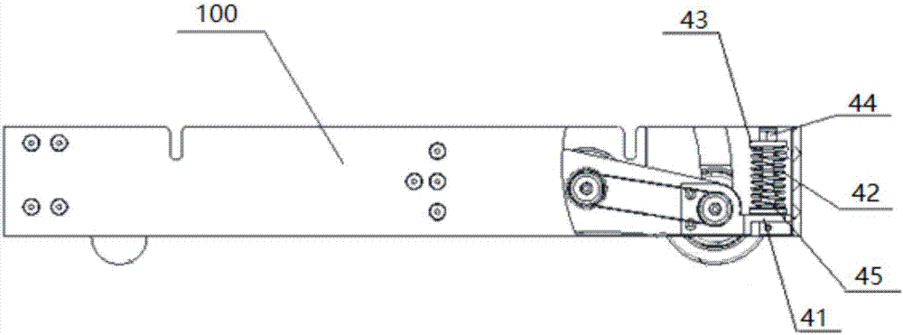
[0071] refer to Figure 4a , the spring support 41 is erected with a spring pull bar 45, the suspension spring 42 is set on the spring pull rod 45, the spring cover 43 is placed on the top of the suspension spring 42, the spring cover 43 is provided with a hole, the hole is aligned with the spring pull bar 45, and the spring pull bar 45 can be placed in the hole middle activity. A fastening nut 44 is placed above the spring cover 43 .

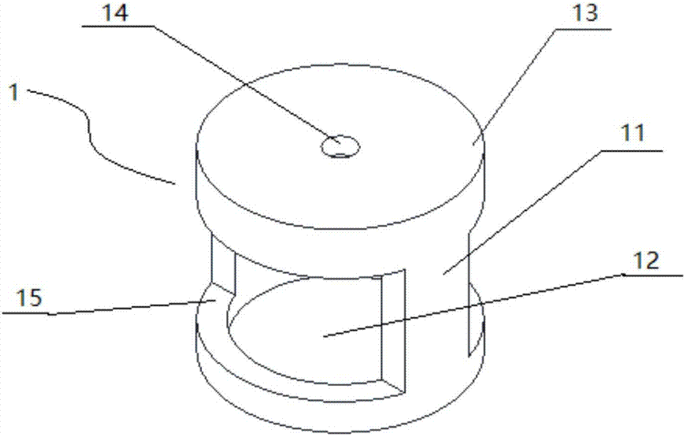
[0072] Put the cylindrical body 1 over the fastening nut 44 and the suspension spring 42, place the auxiliary nut 3 on the upper end surface of the cylindrical body 1, and align the second hole of the auxiliary nut 3 with the first hole 14 of the cylindrical body 1 to assist fastening The rod body of the member 2 passes through the second through hole, the first through hole 14 and the fastening nut 44 in turn, and extends into the inner channel. In the lower half of the rod body, external threads are provided on at least the outer surface pa...

Embodiment 2

[0078] In this embodiment, the rod body of the auxiliary fastener 2 is passed through the first through hole 14, and then the auxiliary nut 3 is sleeved on the rod body of the auxiliary fastener 2 from the outside of the cylindrical body 1, and the auxiliary nut 3 is inserted through the engaging thread. Screw to the vicinity of the cylindrical body 1 or contact with the cylindrical body 1.

[0079] The fastening nut 44 is sleeved onto the rod body from the inner channel of the cylindrical body 1 .

[0080] Referring to Embodiment 1, the fastening structure at the end of the rod body of the auxiliary fastener 2 is connected to the spring pull rod 45 to fix the auxiliary fastener 2 . In this embodiment, the fastening structure may also be:

[0081] The end of the rod body and the top of the spring rod, one is provided with a polygonal, elliptical, bow-shaped (including semicircular) protrusion, and the other is correspondingly provided with a recessed groove of the correspondi...

Embodiment 3

[0087] Referring to Embodiment 1, the fastening structure at the end of the rod body of the auxiliary fastener 2 is connected to the spring pull rod 45 to fix the auxiliary fastener 2 . In this embodiment, the fastening structure may also be:

[0088] The end of the rod body and the top of the spring pull rod, one is provided with a protrusion, the other is provided with a groove, and the wall of the groove is provided with a rivet insertion opening, the protrusion is inserted into the groove, and the rivet is inserted through the rivet insertion opening to displace the protrusion. The part is fixed, so that the auxiliary fastener 2 is fixed.

[0089] After fixing the auxiliary fastener 2, use a tool (such as a wrench) or manually rotate the auxiliary nut 3, the thread on the inner surface of the second perforation of the auxiliary nut 3 engages with the thread on the outer surface of the rod, and under the action of the engaging thread, the auxiliary nut 3 is pressed down Th...


PUM


Abstract

The invention provides a tool for installing a robot trolley suspension spring. The tool comprises a cylindrical body, one end of the cylindrical body is open, and the other end of the cylindrical body is provided with a cylindrical bottom; and the cylindrical bottom is provided with a first penetrating hole. In the process of installing the suspension spring, the cylindrical body compresses a spring cover so as to compress the suspension spring, in the downward compressing process of the spring cover, the top of a sprig pulling rod gradually extends out from a hole in the spring cover, then afastening nut is tightened, and the tool is removed. According to the tool for installing the robot trolley suspension spring, operation is conducted through the tool, laborious manual installing isavoided, and high initial pre-tightening force of the suspension spring is overcome; through the special installing tool and with the help of a screwing-in mode of a screw and the nut, the suspensionspring is compressed to a certain size, then the suspension fastening nut is installed, operation can be completed by one person, and manpower is saved; and after the suspension fastening nut is installed, the installing tool is removed, and the installing tool can be used repeatedly.

Description

technical field [0001] The invention relates to a tool and a method for installing a suspension spring of a robot trolley, in particular to a tool and a method for installing a suspension spring that can be operated by one person. Background technique [0002] The robot car has human-like functions, such as operation function, perception function, walking function, and various actions, especially in high-temperature, toxic, harmful, dangerous, and high-load environments, the robot car can liberate people. [0003] The core of the robot car is the control system, obstacle avoidance system and mobile system. The mobile system can be wheeled, walking, crawler, etc. The wheeled mobile mechanism has the advantages of simple structure and fast speed, and is widely used in planar motion robots. , The wheeled mobile mechanism includes single-wheeled, two-wheeled, three-wheeled, four-wheeled and even more wheeled types. [0004] Due to the complex use environment of the robot car, i...

Claims


Application Information

Patent Timeline
Patent Type & Authority Applications(China)
IPC IPC(8): B25B27/30
CPCB25B27/304
Inventor 韩勇贾强
Owner 浙江众导机器人科技有限公司
Why Eureka
Try Eureka