Melt liquid level control device

A liquid level control and melt technology, applied in the field of molten material transfer equipment, can solve problems such as high energy consumption, broken wires, overflow, etc., and achieve the effect of high liquid level, low speed and large speed

Active Publication Date: 2018-04-06
江苏惠沣环保科技有限公司
View PDF7 Cites 0 Cited by
  • Summary
  • Abstract
  • Description
  • Claims
  • Application Information

AI Technical Summary

Problems solved by technology

[0002] In the production process of chemical fiber spinning, it is generally required that the moisture content of raw materials should be controlled within 2 / 1000. Otherwise, it is easy to cause defects such as broken filaments during the spinning process, which will seriously affect the quality rate. If the moisture control is not good, it may seriously cause production failure.
At present, the factories generally use drying raw materials and then use them in production. The drying time is generally more than 8 hours, which is not energy-saving, and the moisture cannot be controlled to the best.
However, this method consumes high energy and has low processing efficiency.
If the drying operation is to be carried out directly during the processing, it is necessary to use a transfer heating barrel. Extrusion machines in the prior art usually use a constant speed to extrude, and it is difficult to ensure that the barrel is heated in the actual operation. The material is always kept at a certain height, sometimes the material will be short, and sometimes the material will overflow, resulting in waste or normal production, because the melt temperature is very high, and there is a lack of available high-temperature liquid level control devices in the prior art

Method used


Image

  • Melt liquid level control device
  • Melt liquid level control device

Examples


Embodiment Construction

[0013] In order to make the object, technical solution and advantages of the present invention clearer, the present invention will be further described in detail below in conjunction with specific embodiments. It should be understood that the specific embodiments described here are only used to explain the present invention, and are not intended to limit the present invention.

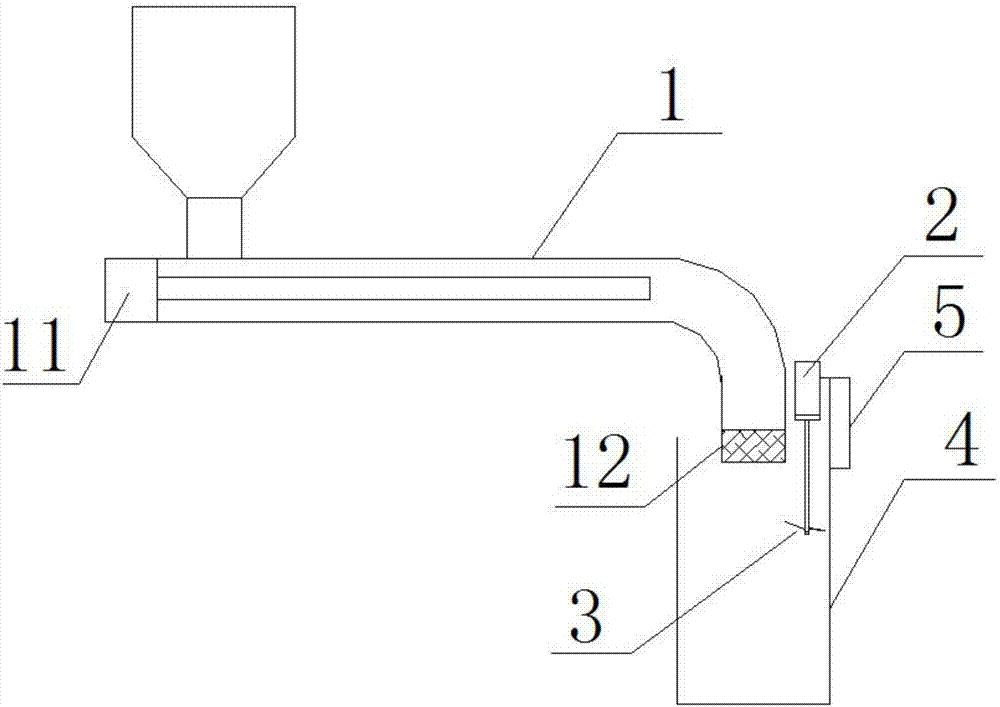
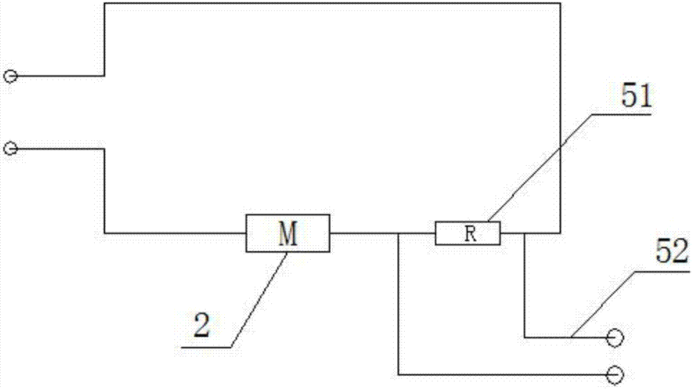
[0014] see figure 1 and figure 2 , a melt level control device, including a small DC motor 2, a barrel 4 and an electrical box 5, a stirring blade 3 is arranged below the small DC motor 2, the stirring blade 3 is located in the barrel 4, and the electrical box 5 is arranged There is an adjusting resistor 51 and a frequency converter control signal connector 52, the adjusting resistor 51 is electrically connected in series with the small DC motor 2, the frequency converter control signal connector 52, and the electrical box 5 is located on the side of the small DC motor 2. Feasibly, a screw extruder ...


PUM


Abstract

The invention discloses a melt liquid level control device comprising a small direct-current motor, a material cylinder and an electrical cabinet. Stirring blades are arranged on the lower portion ofthe small direct-current motor and located in the material cylinder, and an adjusting resistor and a frequency converter control signal connector are arranged in the electrical cabinet. The adjustingresistor is electrically connected with the small direct-current motor in series, the frequency converter control signal connector is electrically connected with the adjusting resistor in parallel, and the electrical cabinet is located at the side edge of the small direct-current motor. The melt liquid level control device has the advantages that the small direct-current motor is arranged in the material cylinder, the stirring blades are arranged at the lower end of the material cylinder, a melt in the material cylinder is stirred, the adjusting resistor is electrically connected in series, afrequency converter for controlling an extruding motor of a screw extruder is connected with the adjusting resistor in parallel, the rotating speed of the screw extruder can be adjusted to be matchedwith the liquid level in the material cylinder, namely, the rotating speed is large when the liquid level is low, and the rotating speed is small when the liquid level is high, and thus the liquid level in the material cylinder can be well controlled to be constant for transferring.

Description

technical field [0001] The invention relates to molten material transfer equipment, in particular to a melt level control device. Background technique [0002] In the production process of chemical fiber spinning, it is generally required that the moisture content of raw materials should be controlled within two thousandths, otherwise defects such as broken filaments will be easily caused during the spinning process, which will seriously affect the genuine product rate. At present, the factories generally use drying raw materials and then use them in production. The drying time is generally more than 8 hours, which is not energy-saving and the moisture cannot be controlled to the best. However, this method consumes high energy and has low processing efficiency. If the drying operation is to be carried out directly during the processing, it is necessary to use a transfer heating barrel. Extrusion machines in the prior art usually use a constant speed to extrude, and it is di...

Claims


Application Information

Patent Timeline
Patent Type & Authority Applications(China)
IPC IPC(8): B29C47/92B29C47/08B29C48/92
CPCB29C48/267B29C48/92Y02P70/10
Inventor 刘卫峰钱日生钱良惠
Owner 江苏惠沣环保科技有限公司
Why Eureka
Try Eureka