Supercharge Your Innovation With Domain-Expert AI Agents!

Sludge treater with lighting function

A technology of processor and sludge, applied in sludge treatment, water/sludge/sewage treatment, chemical instruments and methods, etc., can solve problems such as energy waste

Pending Publication Date: 2018-04-06
江苏和合环保集团有限公司
View PDF0 Cites 0 Cited by
  • Summary
  • Abstract
  • Description
  • Claims
  • Application Information

AI Technical Summary

Problems solved by technology

[0002] The existing sludge mixer is set up on the upper part of the container through the bracket for mixing. The mixer will stir the sludge to a higher position, and the stirred soil is easy to rush out, and at the same time, no mud will fly to a higher position during the mixing process. position, resulting in a waste of energy

Method used


Image

  • Sludge treater with lighting function

Examples


Embodiment Construction

[0022] The specific implementation manners of the present invention will be further described in detail below in conjunction with the accompanying drawings and embodiments. The following examples are used to illustrate the present invention, but are not intended to limit the scope of the present invention.

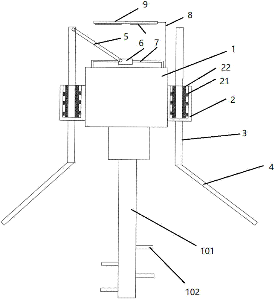
[0023] see figure 1 , a sludge treatment machine with lighting function described in a preferred embodiment of the present invention is characterized in that it includes a motor 1, an annular sliding sleeve 2, a sliding rod 3, a tapered baffle 4, a connecting rod 5, Linear generator 6, magnetic guide rail 7, pole 8, LED light 9;

[0024] The motor 1 is provided with a driving rod 11, and the lower end of the driving rod 11 is provided with a plurality of cutter heads 12;

[0025] The annular sliding sleeve 2 is fixed on the motor 1, the sliding rod 3 is arranged in the annular sliding sleeve 2 and can move up and down along the inner ring, and the bottom of the sliding r...


PUM


Abstract

The invention relates to a sludge treater with a lighting function, which comprises a motor, an annular sliding sleeve, a sliding rod, a tapered baffle plate, a connecting rod, a linear generator, a magnetic guide rail, a vertical rod and an LED (Light-emitting Diode) lamp; the motor is provided with a drive rod; a plurality of tool bits are arranged on the lower end of the drive rod; the annularsliding sleeve is fixed onto the motor; the sliding rod is arranged in the annular sliding sleeve and can move up and down along an annular inner part; the tapered baffle plate is arranged on the bottom part of the sliding rod; the magnetic guide rail is fixed to the top part of the motor; the linear generator sleeves the magnetic guide rail; one end of the connecting rod is rotatably connected with the top part of the sliding rod; the other end of the connecting rod is rotatably connected with the linear generator; the vertical rod is perpendicularly fixed onto the motor; the LED lamp is fixed onto the vertical rod, and is connected with the generator through a guide wire. According to the device, the annular baffle plate is hit by sludge so as to move up and down, a plurality of gears drive the generator to generate electricity, and the LED lamp is powered to illuminate.

Description

technical field [0001] The invention relates to a sludge treatment machine with lighting function. Background technique [0002] The existing sludge mixer is set up on the upper part of the container through the bracket for mixing. The mixer will stir the sludge to a higher position. position, resulting in a waste of energy. [0003] In view of the above-mentioned defects, the designers actively research and innovate in order to create a sludge treatment machine with a new structure with lighting function, so that it has more industrial value. Contents of the invention [0004] In order to solve the above technical problems, the object of the present invention is to provide a sludge treatment machine with lighting function. [0005] Technical scheme of the present invention is as follows: [0006] A sludge treatment machine with lighting function, characterized in that it includes a motor (1), an annular sliding sleeve (2), a sliding rod (3), a tapered baffle (4), a con...

Claims


Application Information

Patent Timeline
IPC IPC(8): C02F11/00
CPCC02F11/00
Inventor 许怡简捷
Owner 江苏和合环保集团有限公司
Features
  • R&D
  • Intellectual Property
  • Life Sciences
  • Materials
  • Tech Scout
  • Unparalleled Data Quality
  • Higher Quality Content
  • 60% Fewer Hallucinations
Learn More