Method for blasting big boulder in artificially dug pile

An artificial digging pile, large-scale technology, applied in the field of blasting, can solve the problems of poor treatment effect, labor and time-consuming, low efficiency, etc., and achieves the effect of good demolition effect, improvement of project quality, and improvement of construction speed.

Inactive Publication Date: 2010-07-21
CHINA 19TH METALLURGICAL CORP
View PDF6 Cites 11 Cited by
  • Summary
  • Abstract
  • Description
  • Claims
  • Application Information

AI Technical Summary

Problems solved by technology

[0002] At present, for the large boulders encountered in the manual excavation piles of industrial and civil building foundations, the commonly used methods include manual chiseling, static blasting, shallow hole blasting, deep hole blasting, electric blasting network blasting, etc., but No matter which method is used, its efficiency is not high, and safety is difficult to guarantee, it is often labor-intensive and time-consuming, and the processing effect is not good

Method used


Image

  • Method for blasting big boulder in artificially dug pile
  • Method for blasting big boulder in artificially dug pile
  • Method for blasting big boulder in artificially dug pile

Examples


Embodiment 1

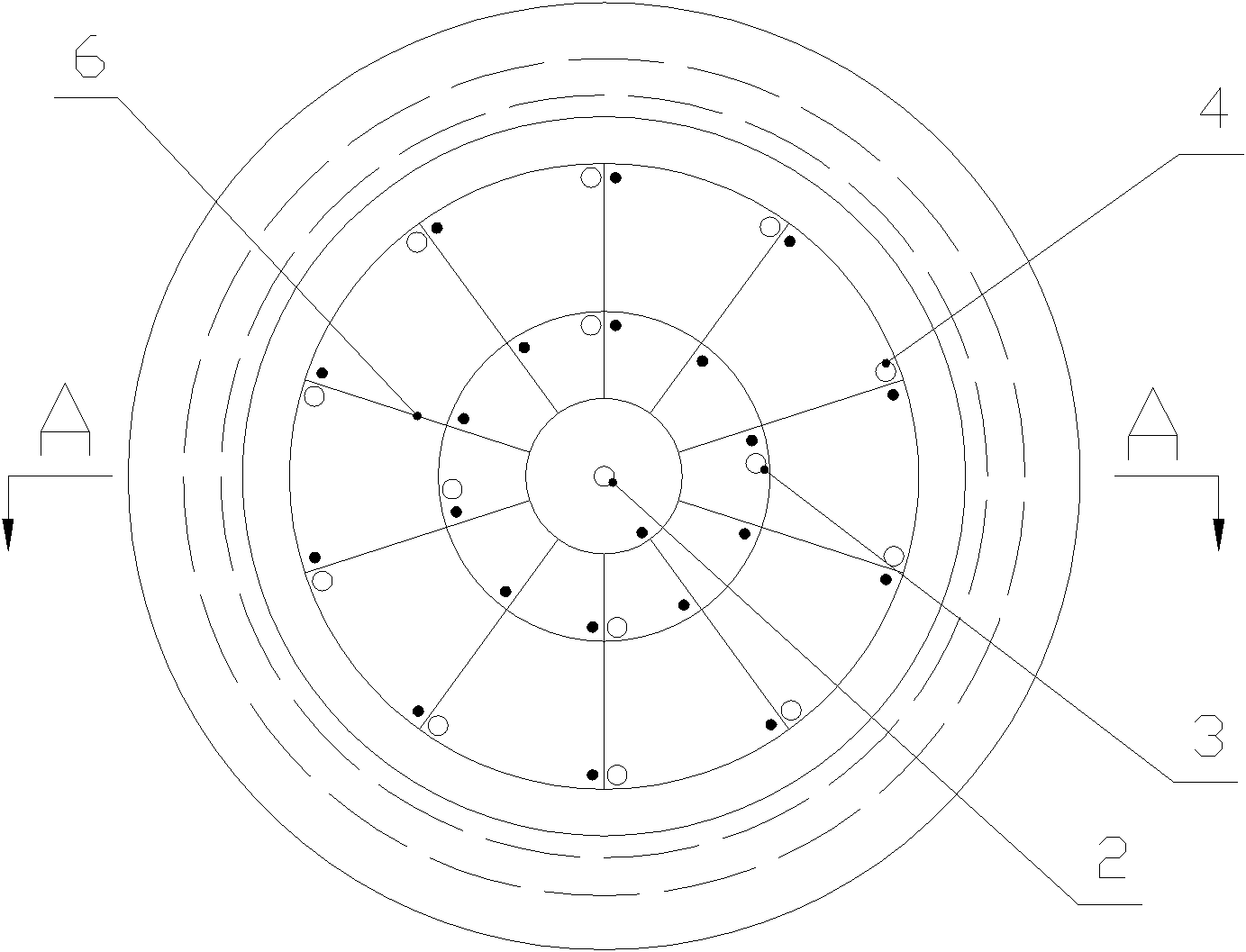
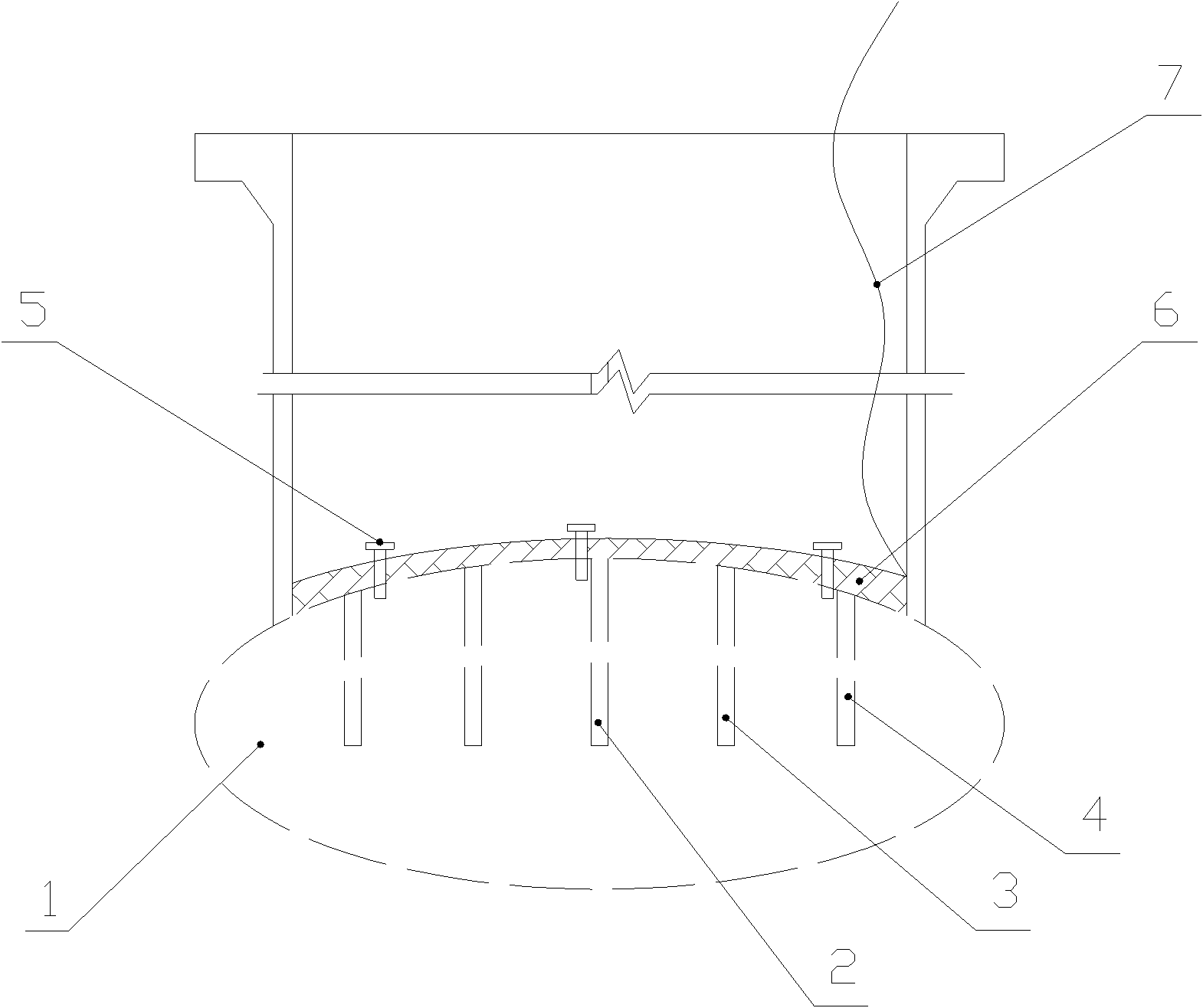
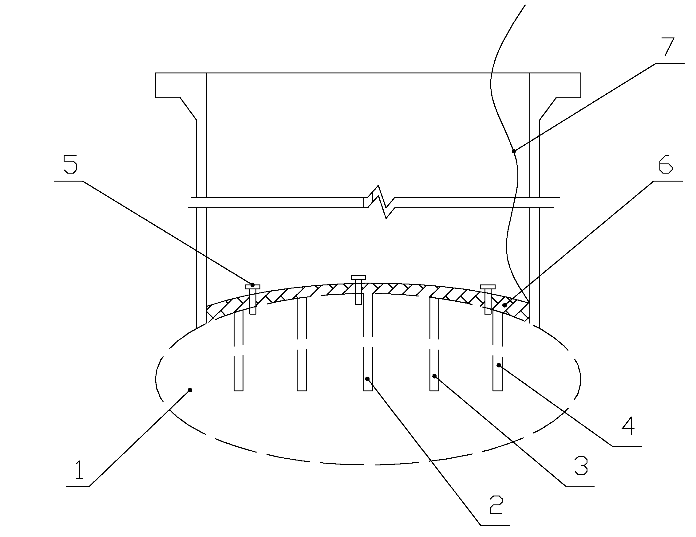
[0031] Embodiment 1: the central blasthole 2 is set to one, and the depth of the central blasthole 2 is 250mm; the distance between two adjacent middle ring blastholes 3 is set to 400mm, and the depth of the middle ring blasthole 3 is set to 200mm; the adjacent two outer ring blastholes 4 The distance is set to 300mm, and the depth of the outer ring blast hole 4 is set to 200mm. After the detonation is completed, the gravel barrier layer 6 of the reinforced grid structure can lift up the blasting part of the large boulder 1 as a whole, and at the same time, no gravel flies out of the artificially dug pile well, and the blasting safety is relatively high.

Embodiment 2

[0032] Embodiment 2: the central blasthole 2 is set to one, and the depth of the central blasthole 2 is 250mm; the distance between two adjacent middle ring blastholes 3 is set to 430mm, and the depth of the middle ring blasthole 3 is set to 200mm; the adjacent two outer ring blastholes 4 The distance is set to 340mm, and the depth of the outer ring blast hole 4 is set to 200mm. After the detonation is completed, the gravel barrier layer 6 of the reinforced grid structure can lift up the blasting part of the large boulder 1 as a whole, and at the same time, no gravel flies out of the artificially dug pile well, and the blasting safety is relatively high.

Embodiment 3

[0033] Embodiment 3: the central blasthole 2 is set to one, and the depth of the central blasthole 2 is 250mm; the distance between two adjacent middle ring blastholes 3 is set to 450mm, and the depth of the middle ring blasthole 3 is set to 200mm; the adjacent two outer ring blastholes 4 The distance is set to 400mm, and the depth of the outer ring blast hole 4 is set to 200mm. After the detonation is completed, the gravel barrier layer 6 of the reinforced grid structure can lift up the blasting part of the large boulder 1 as a whole, and at the same time, no gravel flies out of the artificially dug pile well, and the blasting safety is relatively high.


PUM


Abstract

The invention discloses a method for blasting a big boulder in an artificially dug pile, which can prevent broken stones from flying around and comprises the following steps: a, drilling a plurality of blast holes in the big boulder; b, placing detonators and explosive in the blast holes; c, connecting the detonators in parallel, connecting the detonators with a head lead, leading the head lead out of an artificially dug pile well, and connecting the head lead with a detonating primer; d, arranging a broken stone separating layer in the artificially dug pile well; e, pressing the detonating primer down to detonate and clear blasted stones; and f, repeating steps from step a to step e until the big boulder in the artificially dug pile is completely dismantled. Because the broken stone separating layer is arranged in the artificially dug pile well, in a blasting process, the broken stone separating layer can obstruct the blasted stones and prevent the potential safety hazard caused when the broken stones fly out of the artificially dug pile well. The method is suitable for popularization and application on occasion when big boulders need to be dismantled in artificially dug piles of various construction works.

Description

technical field [0001] The invention relates to a blasting method, in particular to a blasting method for large boulders in manual hole-digging piles. Background technique [0002] At present, for the large boulders encountered in the manual excavation piles of industrial and civil building foundations, the commonly used methods include manual chiseling, static blasting, shallow hole blasting, deep hole blasting, electric blasting network blasting, etc., but No matter which method is used, its efficiency is not high, and safety is difficult to guarantee, it is often labor-intensive and time-consuming, and the processing effect is not good. Contents of the invention [0003] The technical problem to be solved by the present invention is to provide a method for blasting large boulders in manual hole-digging piles, which can prevent the splashing of crushed stones during the blasting process. [0004] The technical scheme that the present invention adopts to solve its techni...

Claims


Application Information

Patent Timeline
Patent Type & Authority Applications(China)
IPC IPC(8): F42D3/04
Inventor 黄成友
Owner CHINA 19TH METALLURGICAL CORP
Why Eureka
Try Eureka