
A Combined Bearing with Limited Swivel Angle

A technology of combined bearings and swing angles, applied in the direction of shafts and bearings, bearing components, rigid supports of bearing components, etc., can solve the problems of increased size, weight, occupation, etc., and achieve the effect of reducing volume and weight

Active Publication Date: 2019-09-13
BEIJING AUTOMATION CONTROL EQUIP INST
View PDF5 Cites 0 Cited by
  • Summary
  • Abstract
  • Description
  • Claims
  • Application Information

AI Technical Summary

Problems solved by technology

Among the rolling bearings, the needle roller bearing is the bearing with the highest bearing capacity under the same volume and weight. In the prior art, the inner and outer rings of the ball bearing have a separate structure and need to occupy a part of the space. In addition, due to its structural characteristics, the needle roller bearing needs to be used. Restricting its axial movement requires the design of the output shaft and its housing assembly, resulting in an increase in size and weight

Method used


Image

  • A Combined Bearing with Limited Swivel Angle
  • A Combined Bearing with Limited Swivel Angle
  • A Combined Bearing with Limited Swivel Angle

Examples


Embodiment Construction

[0047] A limited swing angle combined bearing of the present invention will be described in detail below with reference to the drawings and embodiments.

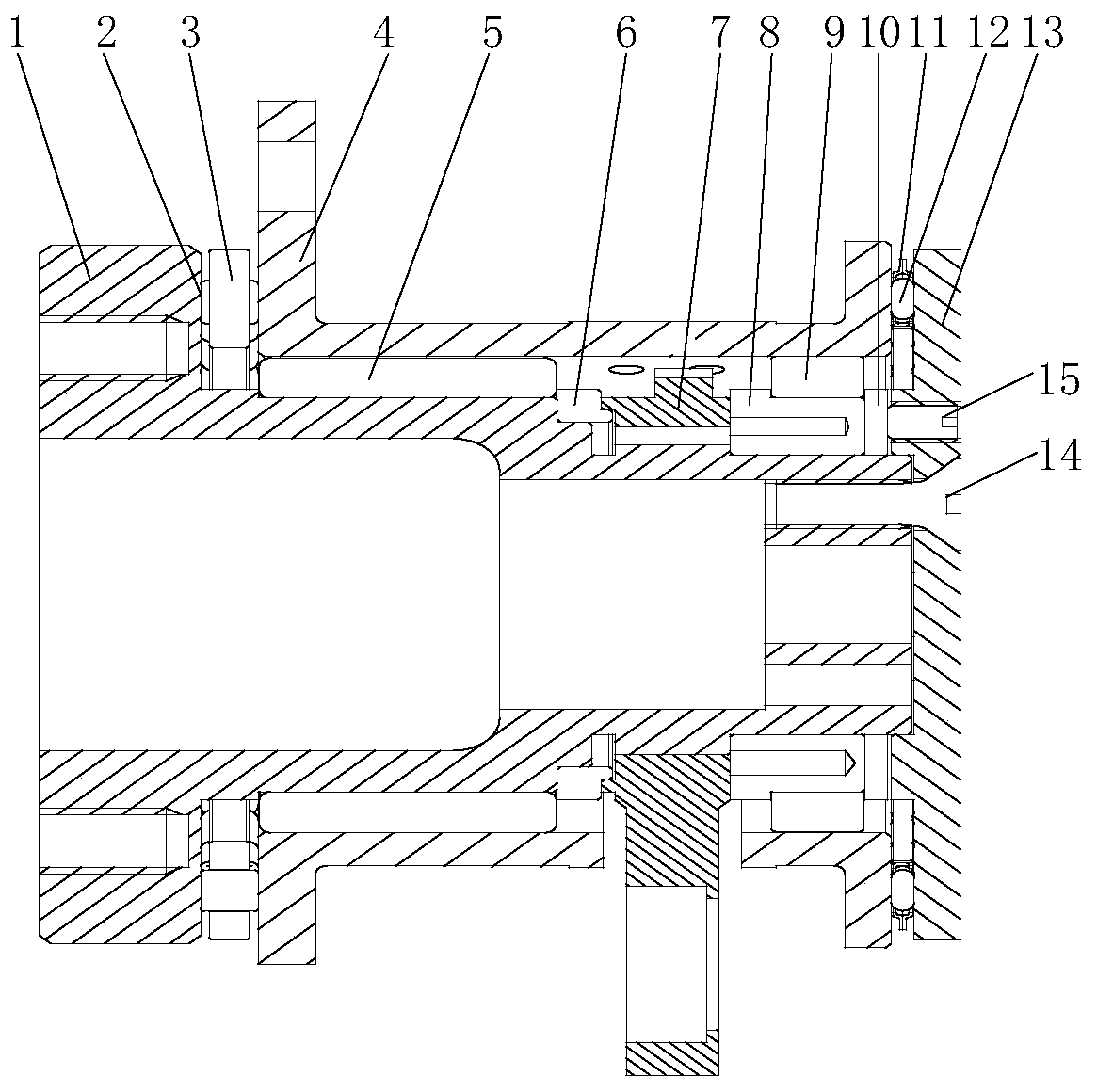
[0048] A combination bearing with a limited swing angle, such as figure 1 As shown, it includes output shaft 1, front face cage 2, front thrust roller 3, support 4, front needle roller 5, front roller retaining ring 6, rocker arm 7, roller inner ring 8, rear end Needle roller 9, rear end roller retaining ring 10, rear end surface cage 11, rear end thrust roller 12 and locking end cover 13.

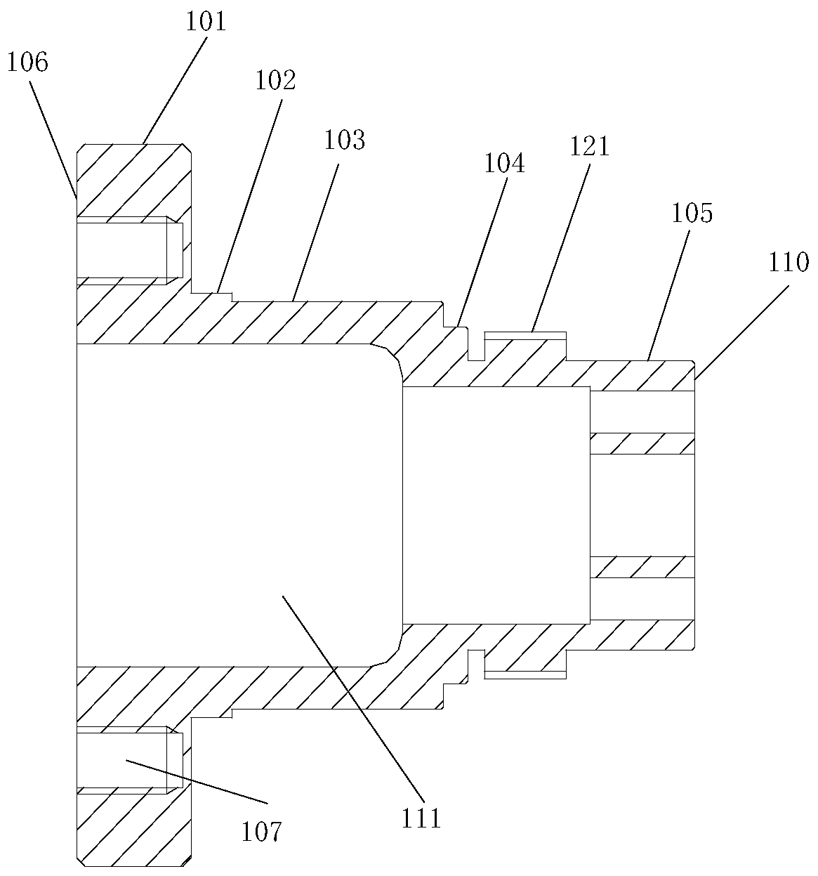
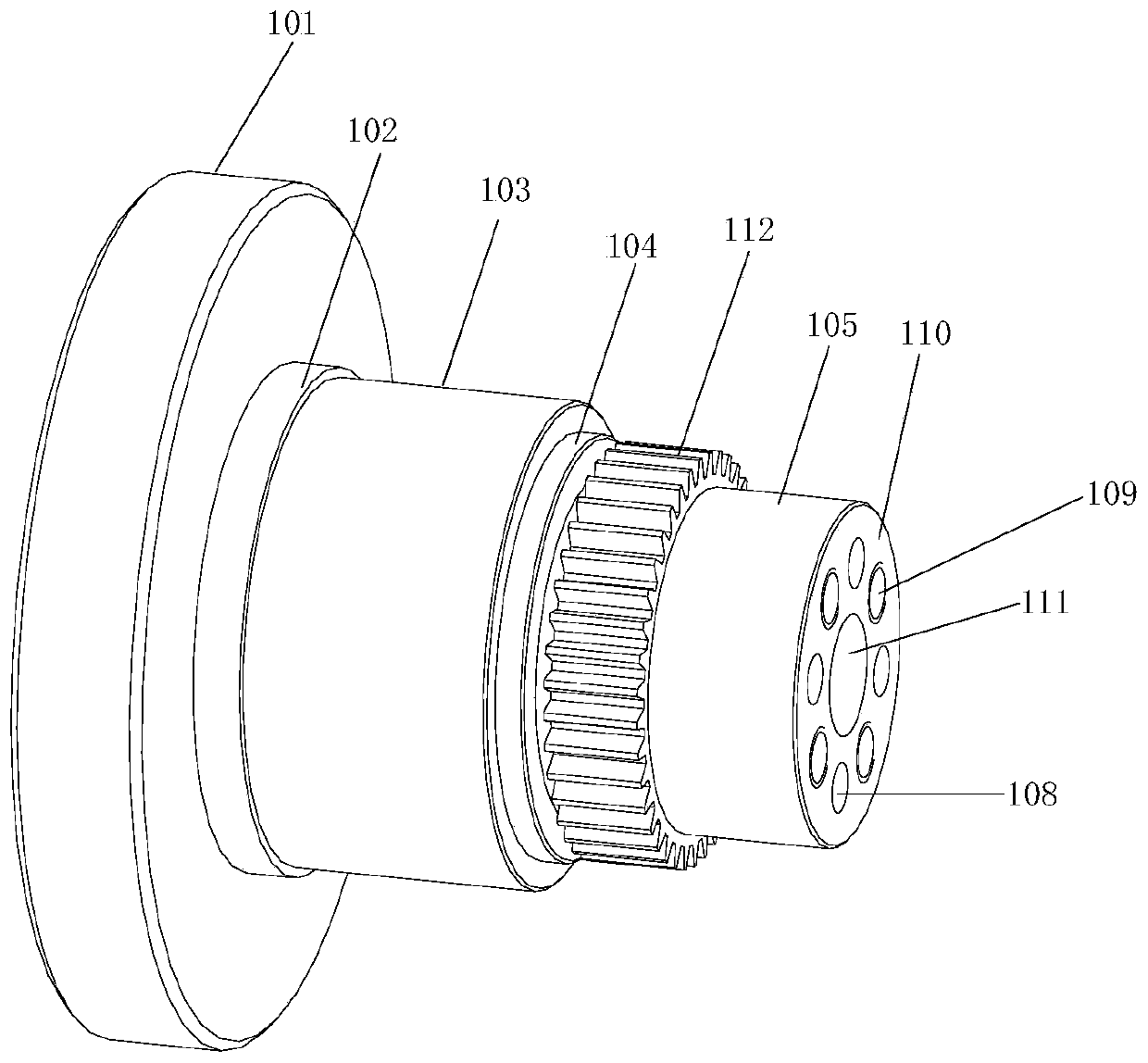
[0049] Such as figure 2 and image 3 As shown, the output shaft 1 is used to output rotary motion and support the rudder surface load, including fixedly connected in sequence from left to right: the first cylinder 101, the second cylinder 102, the third cylinder 103, the fourth cylinder 104 and the first cylinder 104 Five cylinders 105, the diameters of the cylinders decrease successively from left to right, and all the cylinders hav...


PUM


Abstract

The invention belongs to the technical field of steering engines and particularly relates to a finite swinging angle combination bearing. The finite swinging angle combination bearing mainly comprisesan output shaft, a front end face holder, front end thrust rollers, a support, a front end roller pin roller, a front end roller block ring, a rocker arm, a roller inner ring, a back end roller pin roller, a back end roller block ring, a back end face holder, back end thrust rollers, a locking end cap, a fastening screw and a countersunk head screw. The problems that an inner ring and an outer ring of an existing bearing of a discrete structural form need to occupy a part of space, and an output shaft and a shell assembly of the output shaft need to be designed to limit axial movement of theroller pin roller bearing, so that the size and the weight are increased are solved. The finite swinging angle combination bearing adopts functional reuse, the output shaft partially achieves the function of a bearing inner ring, the support partially achieves the function of a bearing outer ring, thus the size and the weight are significantly decreased, and the function of the combination bearingis enhanced.

Description

technical field [0001] The invention belongs to the technical field of needle roller bearings, and in particular relates to a limited swing angle combined bearing. Background technique [0002] With the development of science and the advancement of technology, people have put forward more and more stringent requirements on the volume and weight of industrial products. Especially in the field of aircraft technology, in order to increase the payload of the aircraft, technicians are constantly trying to reduce the volume and weight of the aircraft's own equipment. [0003] Especially when supporting the rudder surface of an aircraft, new requirements require that the rudder surface support mechanism should be small in size, light in weight, large in carrying capacity, and have the function of limiting the swing angle. Among the rolling bearings, the needle roller bearing is the bearing with the highest bearing capacity under the same volume and weight. In the prior art, the in...

Claims


Application Information

Patent Timeline
Patent Type & Authority Patents(China)
IPC IPC(8): F16C35/06F16C33/46F16C33/58
Inventor 李雄峰王永乐王连丛郝卫生曹东海
Owner BEIJING AUTOMATION CONTROL EQUIP INST
Learn More