Proportional one-way flow valve with two-way control

A two-way control, flow valve technology, applied in the field of hydraulic valves, can solve the problems of too large opening of the main spool, failure to reach the flow rate, affecting the application of proportional one-way flow valve, etc., to achieve the effect of satisfying low load use

Active Publication Date: 2019-06-11
上海申花电工器材有限公司
View PDF1 Cites 0 Cited by
  • Summary
  • Abstract
  • Description
  • Claims
  • Application Information

AI Technical Summary

Problems solved by technology

In order to prevent the main spool from opening too much when the load is too large, the throttle area of ​​the orifice controlled by the pilot spool is generally small, so that when the load pressure is 1-25 MPa, the force generated by the pressure difference on the main spool can be reduced. Make the main spool reach the required opening. When the load pressure is lower than 1MPa, the flow area is adjusted by the pilot spool, and the difference between the pressure in the control chamber of the main spool and the load pressure is very small, which results in a very small opening of the spool. Small or even not open, the required flow cannot be reached, which affects the application of the proportional one-way flow valve

Method used


Image

  • Proportional one-way flow valve with two-way control
  • Proportional one-way flow valve with two-way control
  • Proportional one-way flow valve with two-way control

Examples


Embodiment Construction

[0019] The present invention will be further described in detail below in conjunction with the accompanying drawings and embodiments.

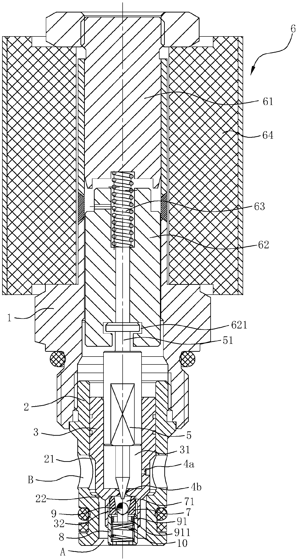
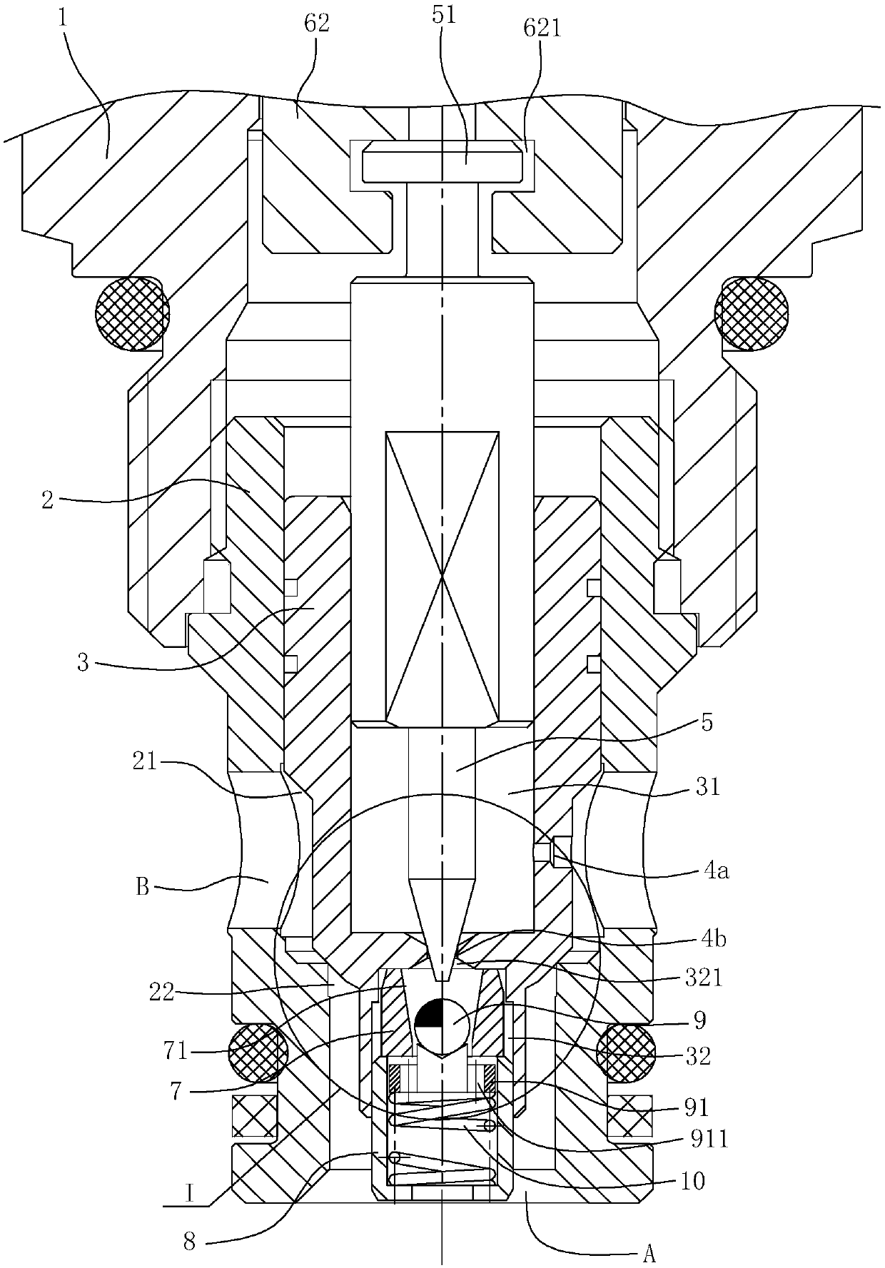
[0020] Such as Figure 1~3 Shown is a preferred embodiment of the present invention.

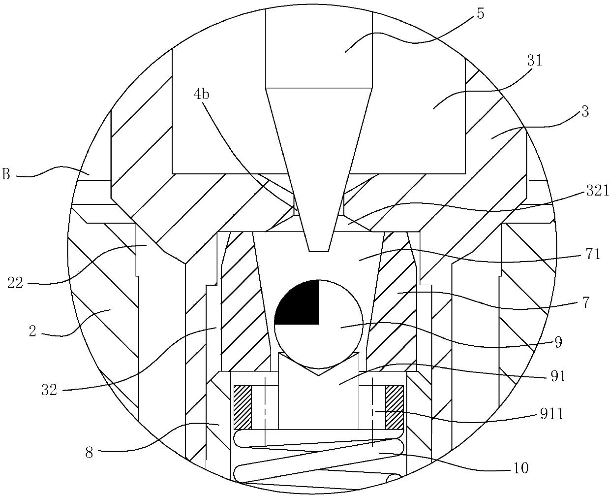
[0021] A proportional one-way flow valve with two-way control, comprising a valve body 1, the lower end of the valve body 1 is threadedly connected with a valve sleeve having an axially penetrated stepped hole 21, the lower end of the valve sleeve 2 opens to form a first oil port A, the valve A second oil port B communicating with the stepped hole is opened on the side wall of the sleeve 2, and the inlet end of the small hole portion of the stepped hole 21 forms a valve port 22 communicating with the first oil port A and the second oil port B.

[0022] The valve sleeve 2 is provided with a stepped main valve core 3, and the outer peripheral conical surface of the main valve core 3 cooperates with the valve port 22, so that the up and down movement of the ma...


PUM


Abstract

The invention relates to a two-way control proportional one-way flow valve, which is characterized in that it includes a valve body, a valve sleeve, and the valve sleeve is provided with a first oil port, a second oil port and a valve port; the valve sleeve is provided with a main valve core , the outer peripheral tapered surface of the main valve core is matched with the valve port, there is a control cavity and an installation cavity inside the main valve core, a first damping hole is opened on the side wall of the main valve core, and a second damping hole is arranged inside the main valve core, The aperture of the first damping hole is smaller than that of the second damping hole; a pilot valve core is arranged in the control chamber, and the pilot valve core is controlled by a proportional electromagnet structure to move up and down, and the lower end of the pilot valve core cooperates with the second damping hole; installation A bushing and a valve seat are installed in the cavity, the bushing has an orifice, the orifice is provided with a steel ball, the valve seat is provided with a spring seat, the steel ball is placed on the spring seat, and the spring seat is supported by a second a spring. The utility model is a proportional one-way flow valve with a more reasonable structure and low cost, which can realize bidirectional proportional control and can satisfy low-load use.

Description

technical field [0001] The invention belongs to the technical field of hydraulic valves, in particular to a proportional one-way flow valve. Background technique [0002] In recent years, proportional one-way flow valves have been used more and more in lifting equipment such as truck-mounted cranes, aerial work vehicles, tractor rotary plows, and electric forklifts. When the equipment stops, the proportional one-way flow valve plays the role of maintaining pressure to prevent the hydraulic cylinder from sliding down; when the equipment needs to descend, the proportional one-way flow valve controls the size of the opening according to the input voltage signal and adjusts the output flow of the hydraulic cylinder , and then control the descending speed of the lifting equipment. The proportional one-way flow valves currently on the market have the following disadvantages: [0003] 1. Only one-way proportional flow control can be realized, that is to say, if the proportional f...

Claims


Application Information

Patent Timeline
Patent Type & Authority Patents(China)
IPC IPC(8): F16K15/18F16K15/04F16K1/00F16K31/40F16K31/06
CPCF16K1/00F16K15/044F16K31/0624F16K31/0675F16K31/40F16K15/1823
Inventor 陈艳艳
Owner 上海申花电工器材有限公司
Why Eureka
Try Eureka